Cutting Thick Steel: Fiber Laser vs CO2
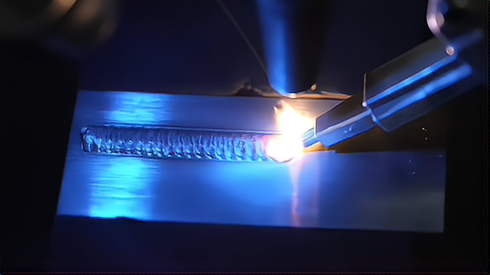
When a shop moves from thin sheet to plate, laser cutting thick steel stops being a question of raw speed and becomes a question of edge quality, gas cost and how much of the plate can be sold as a finished part. Fiber and CO2 sources differ in wavelength, absorption and beam quality, and those differences show up in the cut face, in the assist gas bill and in the thickness each source can handle at a production rate. This article explains what changes above roughly 6 mm, where the two sources separate, and how to choose between them for a given thickness range and tolerance.
Absorption and Beam Quality Set the Ceiling
The first difference is physical. A CO2 source emits at 10.6 micrometers while a fiber source emits near 1 micrometer, and steel absorbs far more of the shorter wavelength. That fact explains why a 6 kW fiber source can cut mild steel at a speed that once required a CO2 source of two or three times the power. A fiber source also reaches the cutting head through a flexible cable, so the beam path needs no mirrors and no purge, which removes an alignment task that CO2 machines require on a routine basis. Electrical efficiency follows the same pattern, with fiber sources converting a much larger share of input power into beam power, and CO2 resonators additionally consume a laser gas mix that has to be replenished on a schedule.
The CO2 advantage lies elsewhere. Its longer wavelength and larger focus spot produce a wider kerf and a more forgiving process on very thick plate, where the molten metal has to be pushed out of a deep and narrow channel. Some shops still prefer the smooth and uniform edge that CO2 delivers on mild steel above roughly 20 mm, and the wider kerf is less sensitive to small changes in focal position. Neither source is uniformly better, which is why the decision usually comes down to the thickness band that carries most of the work.
Where Oxygen and Nitrogen Change the Cut Face
Assist gas decides more about the cut face than the source does. Cutting carbon steel with oxygen adds an exothermic reaction that supplies a large share of the cutting energy, so a lower power source can still get through thick plate, and the cut face takes on the dark and slightly oxidized look that most fabricators accept for structural work. The cost is dross control, a wider heat affected zone and a kerf that widens as the reaction runs away from the beam. Cutting with nitrogen avoids oxidation, gives a bright edge that needs no secondary cleaning, and is the normal route for stainless steel and aluminum, but it demands high pressure and much more power to expel molten metal from a thick kerf.
Pressure for nitrogen cutting commonly falls between about 15 bar and 30 bar, depending on thickness and nozzle design, while oxygen is normally used at low pressure, often between roughly 1 bar and 5 bar. Nozzle condition dominates the result in both cases, because a worn or contaminated nozzle disturbs the gas jet and produces dross long before the optics drift out of alignment. Focus position is the second variable worth fixing during a trial, since a small change in focus offset shifts the balance between cutting speed and dross formation, especially at the thick end of the range.
Gas Consumption and the Real Cost per Meter
The cost comparison is not simply the price of the assist gas. A CO2 machine consumes resonator gas in addition to the assist gas, and its lower wall plug efficiency means more electricity per delivered kilowatt of cutting power. A fiber machine removes the resonator gas entirely and cuts faster at the same thickness across much of the common range, which reduces the minutes of gas flow per part. The counterweight is that nitrogen cutting of thick material needs high flow at high pressure, so the assist gas bill can still be substantial and the compressor or the bulk tank becomes part of the investment.
The practical comparison is cost per meter of cut at a stated thickness and quality level. Build that number from assist gas, resonator gas, electricity, nozzles, protective windows and the labor saved by not aligning a beam path. A single cutting speed or a single hourly rate hides the difference, because a machine that cuts slower but spends less per meter can still win on a specific part.
Thickness, Tolerance and Which Source to Choose
Below about 6 mm the choice is rarely close, and fiber wins on speed, running cost and floor space. Between roughly 6 mm and 20 mm in carbon steel the answer depends on the edge the customer accepts and on whether oxygen cutting is allowed, because fiber with oxygen can replace CO2 across most of that band. Above roughly 20 mm the decision needs a cutting trial on the actual plate, since alloy, surface scale and flatness matter as much as thickness. Tight angularity and a small heat affected zone favor fiber with nitrogen at high power, while a shop that mostly cuts very thick mild steel and values a familiar edge may still find a CO2 machine adequate, provided the gas supply and the maintenance routine are acceptable.
Before committing capital, cut a set of plates that represent the thickest and the fussiest work the shop expects, and measure kerf width, dross, perpendicularity and heat affected zone on each. Record assist gas flow and electricity used during those cuts, then compare cost per meter rather than cost per hour. If the trial is close, let the pattern of future orders decide, because a source that is marginal today will only become more marginal as tolerances tighten and gas prices move.
Comments (0)
No comments yet.
Sign in to join the discussion.