Laser Welding Robot Maintenance: A Practical Schedule
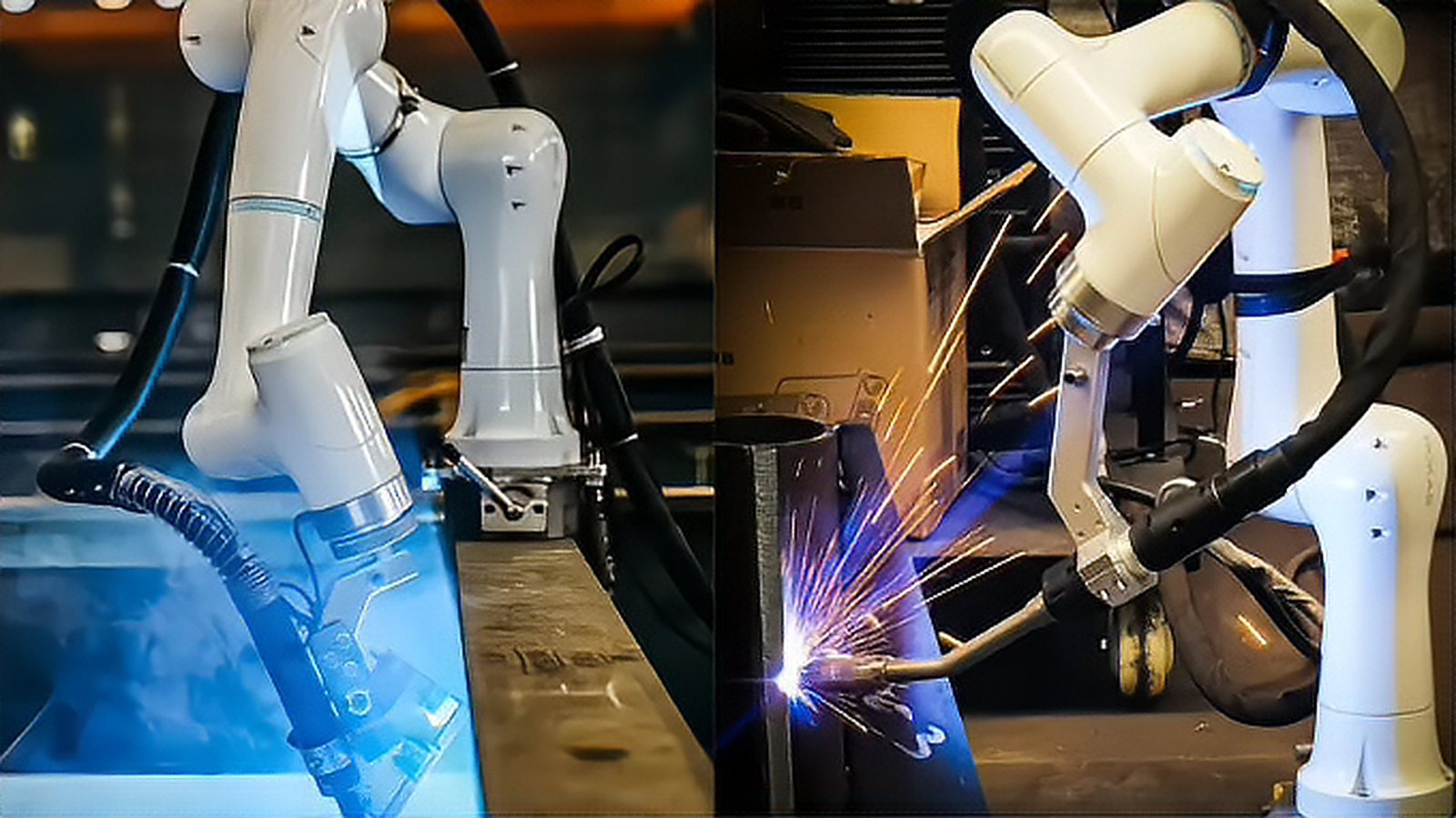
Laser welding robot maintenance is usually copied from a machine manual into a spreadsheet, and that approach collapses the first time a production planner asks which task can wait until the weekend. A schedule that survives a three shift operation is built from failure modes, from the cost of missing each one, and from the time a check actually takes on the floor. This article explains what fails on these cells, what belongs in a shift check, a weekly routine and a quarterly service, and how to convert the list into a system that keeps working when the plant gets busy.
Know What Actually Fails
The items that stop a laser welding cell are the protective cover slide, the focusing optics behind it, the fiber end faces, the coolant loop, the extraction filter, the robot harness and dress package, and the calibration of the tool center point. Each has its own signature. Contamination on the cover slide shows up as a slow loss of power at the work plane and a rising back reflection on a monitoring channel. A dirty fiber connector usually appears as an immediate power drop after any service that disturbed the delivery cable.
Coolant temperature that creeps up while the setpoint holds steady points to a loaded filter or a fouled heat exchanger. A program that gradually produces shallower penetration usually points to a focal position shift caused by thermal growth in the head or by a loose optic mount. Grouping tasks by the signature they prevent is more useful than grouping them by calendar, because it tells a technician what to look at when the first symptom appears.
Every Shift and Every Day
Start with the parts that protect everything else. Inspect the cover slide and the nozzle for spatter and replace the slide whenever there is doubt, since its cost is trivial next to a contaminated optic. Verify shielding gas flow and, where a nozzle shoe is used, the condition of its seal. Check the extraction system for reduced flow or rising differential pressure, and confirm the chiller is inside its temperature and flow limits before the first production weld.
Verify the tool center point with a calibration pin and confirm the robot returns to its reference position. Cut or section a first part and record the penetration, and keep that record, because a trend line over several days identifies drift long before a reject appears. A functional test of the guard interlocks and the shutter belongs at the start of a shift or at the start of a new program, along with a check that the emergency stop chain terminates emission rather than only stopping motion.
Weekly Tasks
Clean the optics only when the schedule calls for it, using the method and the solvents the laser manufacturer specifies, because unapproved solvents attack optical coatings. Trace the delivery fiber over its full route and look for tight bends, abrasion and strain at the connector boots, then check that the strain relief is doing its job. Read the coolant conductivity on units that use deionized water and replace the cartridge when it leaves the specified range.
Change or clean the extraction filters and empty the spatter collection tray. Review the alarm and monitoring log for warnings that recur without stopping production, since those are the ones that turn into downtime. Check the head mounting bolts and the flange with a torque wrench, and inspect the gas lens and its seals.
Quarterly and Annual Service
Measure the power delivered at the work plane with a calibrated meter and compare it with the commissioning record, which separates optical degradation from process drift. Check focus position and, if the application is sensitive to it, beam quality. Verify the shutter response time and the interlock chain with the result written down, replace the coolant at the chiller manufacturer interval, and confirm robot calibration, backlash and home position against the commissioning data. Replace harness and dress package items that have reached their stated life, and re validate every safety function with a record. This is also the moment to reopen the risk assessment if the part mix, the optics or the fixtures have changed since the last review.
Turn the Schedule Into a System
Energy isolation for any work behind a guard follows a written control procedure, which in the United States means an energy control program under OSHA 1910.147 (https://www.osha.gov/laws-regs/regulations/standardnumber/1910/1910.147). For a laser cell that procedure has to cover the beam as well as electrical energy, so the source is disabled, the shutter state is confirmed and the key is under the control of the person doing the work. The manufacturer is required to supply user information covering maintenance and service for the laser product, and that document, not a forum post, is the baseline for the schedule (https://webstore.iec.ch/en/publication/3587).
Hold spares that cover the common failures, which are cover slides, nozzle tips, filter elements, seals, a chiller cartridge and, where lead time is long, a spare delivery fiber. Keep every entry in one log with the part serial numbers so that a field question can be answered from records, and move tasks from fixed intervals to condition triggers as the data improves. A rising back reflection signal, a chiller temperature trend or a growing alarm count are all better triggers than a calendar date.
Write the schedule with the technicians who will execute it, then walk the cell with them and time each task. If a shift check takes longer than ten minutes nobody will do it properly, so move anything slower into the weekly block and keep the daily work short, visible and signed.
Comments (0)
No comments yet.
Sign in to join the discussion.