Planning a Laser Robot Cell: Layout and Floor Space
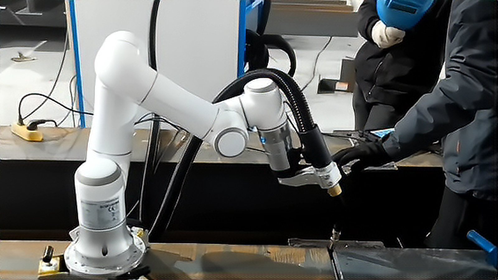
A laser welding cell layout is decided long before the robot model is chosen, because the safety enclosure, the part flow and the service access fix the floor plan and everything else has to fit inside it. Teams that start from the robot reach envelope often end up with a cell that is awkward to load and expensive to maintain, and the cost of changing the plan rises sharply once concrete, power and exhaust ducts are in place. This article covers the planning sequence for a single robot welding cell, from part flow and station arrangement to enclosure boundaries and the clearances that are easy to leave off a drawing.
Start With the Part Flow, Not the Robot
The first drawing should show how a part enters, gets located and leaves the cell, not where the robot stands. A single station cell is the simplest and cheapest option, but the robot is idle while the operator unloads and reloads, which is acceptable only when the weld time is short or the batch is small. A two station arrangement with a rotary table or a shuttle lets one position be welded while the other is loaded, and the gain in output per shift usually justifies the extra mechanics. A turntable carries the fixture and the part on a rotating axis, which is compact but adds a large moving mass and a rotating cable path. A linear shuttle keeps the fixtures on a straight track and is easier to guard and to service, at the cost of a longer footprint.
The part flow also decides the operator position. Loading from the front keeps the walk short and lets one person tend two cells, while loading from the side separates the operator from the robot and the beam path, which is easier to defend in a risk assessment. Whatever the arrangement, freeze the fixture design at this stage, because the largest fixture and the swing of its clamps set the interior dimensions of the enclosure.
Where the Laser Source Sits
One of the few planning advantages of a fiber source is that the resonator can stand outside the safety enclosure and deliver the beam through an armored fiber optic cable. That keeps the interior clear, removes a heat load from inside the cell and simplifies service, since the source can be opened without breaking the enclosure. The cable is the constraint, with a minimum bend radius and a limited length, and every extra meter adds loss and cost. Route it in a gentle arc with a strain relief at the head, keep it away from the fume extraction duct and from sharp edges, and provide a service loop that a technician can reach without removing other equipment.
Support equipment belongs on the same plan. The chiller, the control cabinet, the shielding gas supply and the fume extraction unit each need floor space, service clearance and a utility connection, and some can be placed outside the enclosure. Decide early which items stay inside, because every square meter inside the enclosure is more expensive to build, to cool and to keep light tight.
Enclosure, Interlocks and the Safety Boundary
The enclosure turns a Class 4 process into a machine that people can work next to, so its walls are the real safety boundary and the floor plan should be drawn around them. In the United States the governing consensus document is ANSI Z136.1, which describes the nominal hazard zone and the controls expected for a Class 4 laser, while ANSI B11.21 covers machine tools that use lasers for material processing. OSHA points to both from its laser hazards pages, and eye and face protection appears in the general industry standards (https://www.osha.gov/laser-hazards/standards). The practical result for a layout is that every opening large enough for a person or a hand must be guarded or interlocked, and viewing windows must be specified by optical density at the working wavelength.
That boundary has to be maintained over time. Leave space in front of every door for it to swing fully, and keep a clear path from the cell to the nearest exit. Fume extraction is part of the same layout question, because the capture point belongs as close to the process zone as the robot motion allows, and a hood placed on the far side of the enclosure will pull the plume across the operator door.
Reach, Access and the Space Nobody Budgets
Robot reach is a starting point, not a plan. The usable envelope is smaller than the published figure once the torch, the dress pack and the tooling are included, and the robot needs clearance behind and beside it for service. A common planning figure for service access along the back of a robot is roughly 600 mm to 800 mm, and the enclosure has to be sized for that clearance even though production never uses it. Check the motion envelope at the extreme positions of the program, because a torch that swings into a panel during a service move is a repair waiting to happen.
Three other items are routinely underestimated. The first is floor space outside the cell for fixtures, part staging and an inspection table, which is where a generous looking cell becomes cramped. The second is cable and hose management, which decides how often the dress pack is replaced. The third is room for a future second station, since a cell with a blank wall on one side cannot grow.
Plan the cell around a specific part family and a specific takt time, then draw the enclosure last so it wraps the process instead of constraining it. Walk the drawing with the operator and with the maintenance technician before it is approved, and mark the service clearances and the door swings in a different color so they are not treated as usable floor. Confirm the guarding approach against ANSI Z136.1 and record the assumptions in the risk assessment, so the layout can be defended when the part mix changes.
Comments (0)
No comments yet.
Sign in to join the discussion.