Laser Welding Thin Sheet Metal: Gap Bridging and Fixturing
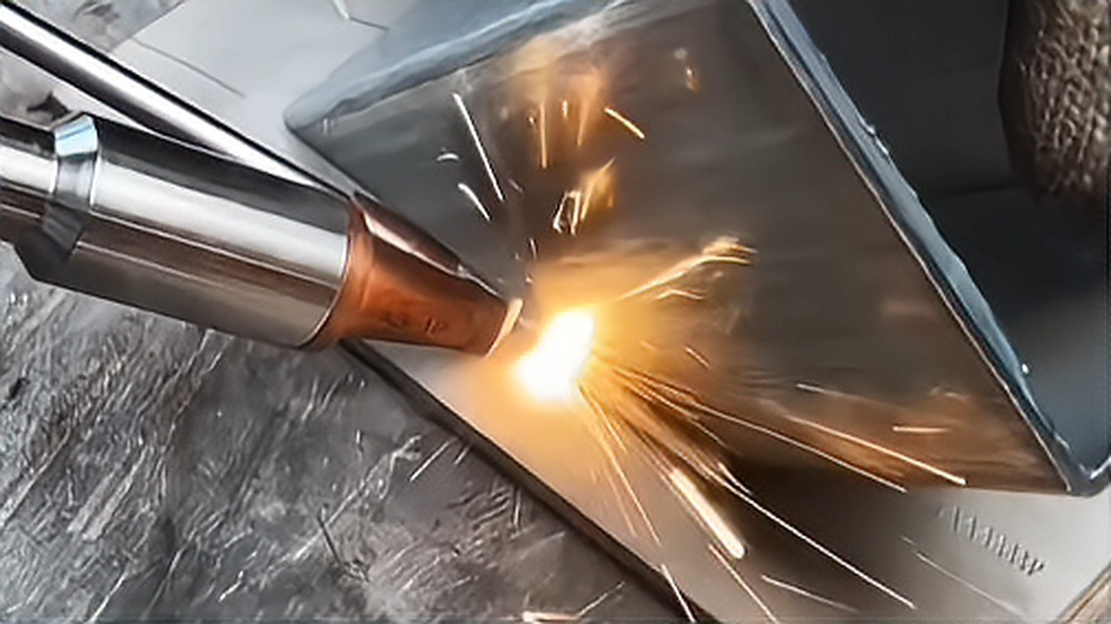
Laser welding thin sheet metal in the 0.3 to 1 mm range demands a level of joint preparation and fixturing precision that thicker stock simply does not require, because the process window for gap, mismatch and heat balance is razor thin. This article covers the gap tolerance that thin sheet actually allows, what happens when the gap exceeds it, how beam oscillation and focus adjustment can compensate for imperfect fit, and the fixture design principles that keep thin parts flat and cool enough to weld without distortion.
Gap Tolerance and What Happens When It Is Exceeded
The general rule for autogenous laser welding, meaning no filler wire, is that the joint gap should not exceed roughly 10 percent of the sheet thickness. For 0.5 mm sheet, that means a gap of 0.05 mm, which is tighter than most stamped or sheared edges can hold without secondary processing. When the gap is within tolerance, the melt pool from each edge meets and fuses with a slightly concave to flat crown. When the gap exceeds 10 percent of thickness, there is not enough molten metal to fill it, and the result is an underfilled bead, a concave crown, or a hole through the joint. At gaps approaching the sheet thickness, the beam passes straight through without any fusion at all.
This tight tolerance is the central challenge of thin sheet laser welding. A stamped blank that varies by 0.1 mm in flatness or edge quality is already outside the window for 0.5 mm material. The solutions fall into two categories, improving the fit before welding, and using beam manipulation to bridge a gap that cannot be fully eliminated.
Beam Oscillation and Focus Position as Gap Compensation
Beam oscillation, often called wobble welding, sweeps the focused spot in a controlled pattern, commonly circular or transverse linear, while traveling along the seam. A circular wobble with a diameter of 0.3 to 0.6 mm on a 0.5 mm sheet effectively widens the melt pool and gives the process a far larger gap tolerance, sometimes bridging gaps up to 20 or 25 percent of thickness without underfill. The oscillation also stirs the melt pool, which can improve wetting and reduce porosity on galvanized or oily surfaces. The cost is a slightly wider bead and somewhat lower travel speed, because the beam covers more distance per unit of seam length.
Focus position plays a supporting role. Defocusing slightly, by moving the waist a fraction of a millimeter above the surface, widens the spot and distributes energy over a larger area, which helps bridge small gaps and reduces the risk of burn through on the thin edge of a mismatched joint. On parts with variable gap along the seam, a combination of moderate wobble and slight defocus gives the most forgiving window. Pushing either too far, however, drops energy density below the threshold for a stable keyhole, and the weld shifts to conduction mode with shallow penetration and a wide bead.
Fixture Design Principles for Thin Sheet
Fixtures for thin sheet welding serve two purposes, holding the parts in intimate contact along the seam, and providing a heat sink that prevents warping. The clamping force should be applied as close to the weld line as possible, because any visible gap at the seam is already near the limit. A typical arrangement uses copper alloy fingers or bars spaced at 10 to 20 mm intervals along the seam, each pressing down with enough force to close the gap without denting the sheet. The exact force depends on material and thickness, but the goal is to have the edges touching or nearly touching under the beam.
The heat sink matters as much as the clamp. Thin sheet warps because the heated zone expands against cooler surrounding material and buckles upward. A copper backing bar directly under the seam conducts heat away from the weld and supports the root, preventing sag and burn through. For joints with a backing, the bar should have a shallow groove under the seam, roughly 0.5 to 1 mm wide and 0.2 mm deep, to give the root a place to form without sticking to the fixture. Without a backing bar, burn through is the most common failure on sheet below 0.4 mm, and no amount of parameter tuning will fully compensate for the lack of support.
Deformation Control Strategies
Controlling distortion starts before the fixture, in the part preparation and welding sequence. Parts should be deburred and cleaned before clamping, because burrs hold the edges apart and oil vaporizes into the weld causing porosity. On a long seam, tack welding at intervals before the full pass holds the edges in register and prevents the seam from opening as the weld progresses. For symmetric parts, welding from the center outward or alternating sides of a symmetric assembly balances the thermal stresses and keeps the overall flatness within tolerance. Heat input should be minimized to the extent that penetration and gap bridging allow, because every additional watt second of energy is extra thermal strain the fixture has to absorb.
On parts where distortion is persistent despite good fixturing, consider a stitch or segmented weld pattern, welding short sections with cooling time between them. This sacrifices some cycle time but can hold flatness within specification on parts that would otherwise require post weld straightening.
Measure your gap before welding, using a feeler gauge at several points along the seam, and if it exceeds 10 percent of sheet thickness, either rework the edge or add wobble before running the job. Design your fixture with copper backing under every thin sheet weld, and place clamps within 10 mm of the seam line. Run a tack pass on any seam longer than 50 mm to prevent gap opening during the weld. These steps cost minutes in preparation and save hours in rework.
Comments (0)
No comments yet.
Sign in to join the discussion.