Laser Cladding and Additive Repair with Robots
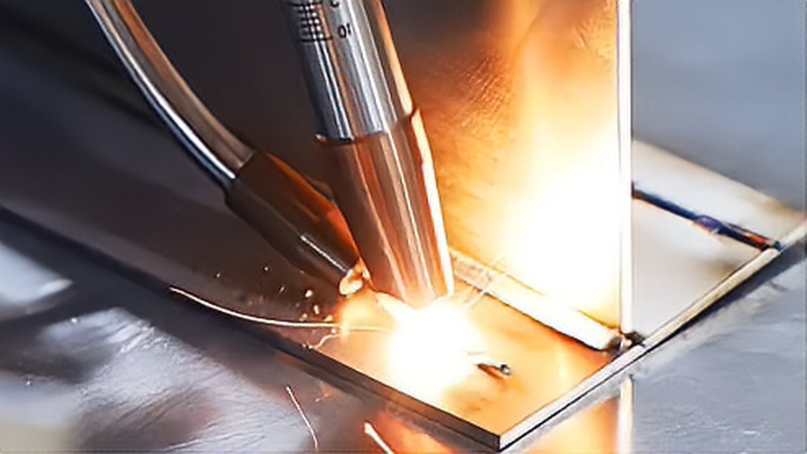
A laser cladding robot is not a welding machine that happens to run slower. It is a repair tool that rebuilds a worn or undersized surface with a controlled amount of new metal, and its value comes from how little it disturbs the part underneath. Shafts, forming dies, mold cavities and hydraulic rods are typical candidates, and the decision is always the same: how much dilution the part can tolerate, how much heat it can absorb without distorting, and what has to be machined afterwards. This article works through those trade offs and the process window that follows from them.
How the Deposit Forms
A cladding head delivers the beam and the filler to the same small spot on the workpiece. Powder arrives through a coaxial or off axis nozzle and is melted in the beam before it reaches the surface, while a thin layer of the substrate melts at the same moment so that the two fuse. Wire can be used instead of powder. Typical industrial settings for a robot mounted head sit between roughly 500 W and 3000 W, with travel speeds commonly between 300 mm and 1200 mm per minute, spot diameters around 1 mm to 3 mm and single layer thicknesses from a few tenths of a millimeter up to about 1.5 mm. Adjacent tracks are overlapped by roughly 40 percent to 60 percent to build a continuous layer without valleys between passes. Because those numbers interact, the practical approach is to fix the deposit geometry you need and then tune power, speed and feed rate together.
Dilution and Heat Input
Dilution is the fraction of the deposit that comes from the substrate rather than from the filler, and it decides whether a repair behaves like the original part. High dilution means the base metal has altered the chemistry of the deposit, which can soften a hard facing alloy or weaken a corrosion resistant layer. Common practice is to keep dilution low, often in the range of a few percent to about ten percent, by raising travel speed, lowering power and avoiding an overlap that remelts too much of the previous track. The opposing pressure is bonding: too little melting of the substrate gives a mechanical contact rather than a metallurgical bond, and the layer lifts in service. Heat input also drives distortion and cracking. Large parts benefit from preheat, often a few hundred degrees Celsius for tool steels and high carbon grades, and from slow cooling under an insulation blanket rather than free cooling in a cold shop. On long shafts the deposit sequence should be balanced around the axis so that shrinkage does not bend the part, and the cooling time between passes belongs in the recipe.
Powder or Wire
Powder gives finer control over composition and layer thickness, which suits small repairs on dies and mold edges where only a few tenths of a millimeter are needed. The trade off is that not all of the powder lands in the melt pool, so the unused fraction has to be collected. Figures commonly quoted for coaxial nozzles fall between 60 percent and 90 percent capture, but the real number depends on the nozzle, the standoff and the gas flow, so it should be measured on the actual head. Overspray also makes masking, extraction and powder handling part of the cell design. Wire avoids most of that, is easier to keep clean and deposits more efficiently, but the layer tends to be thicker and it is harder to hold a thin, precise deposit at the edge of a repair. A powder head with a changeable nozzle set is a common compromise for mixed work, while wire suits larger build up on rotating parts.
Programming a Path on a Part That Has Worn
The geometry of a worn part is unknown when the job is quoted, which is the central programming difficulty in repair cladding. The practical answer is to measure before you deposit. Laser scanning or a touch probe on the robot maps the worn surface, the scan is compared with the nominal model, and the difference sets the deposit thickness for each track. A positioner or a rotary axis is usually added so the head can work at a consistent angle, and the controller has to coordinate that external axis with the arm so travel speed stays constant around the circumference. The path must also respect the wrist limits of the arm, because a coaxial head is bulky and an awkward approach angle changes the powder focus. The first and last millimeters of every track need attention as well: ramping power down at the end avoids a crater, and a slight overlap at the start prevents a low spot that shows up after machining.
Qualifying the Repair
A cladding job is finished only when the repaired part can be inspected and accepted. The usual checks are a hardness traverse across the deposit and the interface, a bond examination such as dye penetrant, ultrasonic or magnetic particle testing, and a dimensional check after grinding. For critical parts, a witness coupon processed with the same recipe is often tested destructively so that the production part does not have to be cut. Because a machining allowance of a few tenths of a millimeter is normally left on the deposit, the recipe should leave that allowance consistently rather than the minimum that happens to fit.
Before you commit to a repair route, cut a section from a scrap part, clad it with the intended recipe and have the section examined for dilution, porosity and cracks. That test costs far less than a rejected batch of repaired parts. Then write the alloy, the layer thickness, the preheat and the inspection method into the work instruction, so a second shift can repeat the process.
Comments (0)
No comments yet.
Sign in to join the discussion.