Seam Tracking and Vision for Laser Welding Robots
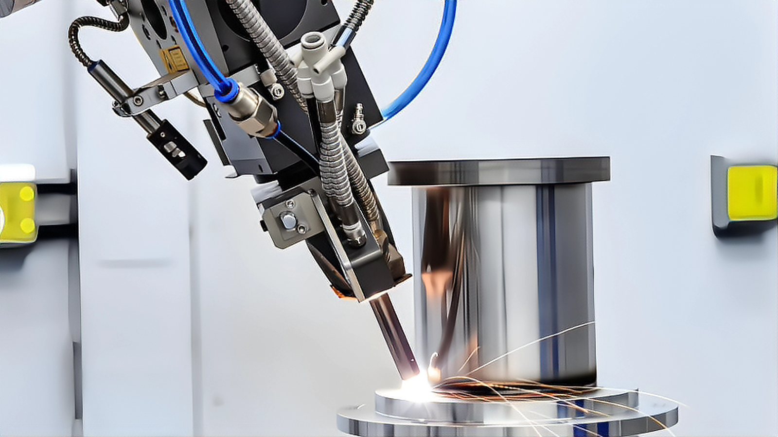
Laser seam tracking exists because a robot that follows a taught path cannot keep up with real parts. Blanking tolerance, springback, distortion from tack welds and fixture wear all move the joint between the teaching run and the production run, and a focus spot between 0.2 mm and 0.6 mm has no room for that error. This article explains how triangulation tracking and camera based vision differ, what each one can measure and how to choose between them for a given joint.
A taught path records where the joint was on the day of teaching, not where it will be at hour three of a shift. On a large stamped assembly the edge of a lap joint can wander several tenths of a millimeter along one seam, and the gap opens and closes as the clamps and the weld sequence do their work. Tracking closes the loop by measuring the joint shortly before the beam arrives and shifting the path to match.
How Triangulation Tracking Works
A triangulation sensor projects a laser line onto the workpiece at an angle and images the scattered light on a detector. The position of the line in that image gives a profile, and the profile contains the joint edges, the height of the surface on each side and the gap between them. In welding the sensor sits on the head and looks ahead of the pool, commonly 20 mm to 60 mm in front, so the controller can correct before the beam arrives. Industrial units commonly sample at several hundred hertz to a few kilohertz, repeat within a few hundredths of a millimeter and work at standoffs between roughly 50 mm and 200 mm. The weaknesses are surface sensitivity and window contamination: shiny aluminum, copper and oil films scatter light in ways the profile algorithms handle badly, and spatter build up on the protective glass degrades the measurement long before the sensor stops working. An aggressive wobble can also throw enough process light back into the optics to disturb the reading.
What Camera Vision Adds
A camera based system, usually a three dimensional camera or a structured light scanner, takes a wider view. It can find a seam that is not where the program expected it, confirm the right part is in the fixture, measure a varying gap and inspect a tack weld before welding begins. Field of view and working distance are far larger than a triangulation sensor allows, so one camera can also locate the part. The price is latency, because building a three dimensional image takes longer than reading a profile. Ambient light from a neighboring arc, fume and spatter on the lens all reduce image quality, so shielding and air purge belong in the design. Camera vision earns its cost when the task includes inspection, or when the seam must be found from scratch on a rough casting or a hand prepared repair groove.
Matching the Sensor to the Joint
Start with the joint and the variation you expect, not with the sensor catalog. A tight butt joint on clean, repeatable parts may need no tracking at all. A lap joint on stamped parts with a varying gap is the classic case for triangulation, because the geometry is simple and the correction must be fast. A fillet on a large weldment, a repair groove cut by hand, or a seam that must be found on an unmachined casting points toward camera vision or toward a scan first, weld second sequence. Material matters as much as geometry: aluminum and copper favor better filtering and a cleaner optical path, or a process that tolerates gap variation, such as wobble welding. If the joint can be reached from a fixed direction at a short standoff, triangulation is usually the cheaper and faster answer. If the joint height varies across a three dimensional part, check the measurement range and the field of view against the worst case before committing.
Integration Details That Decide Success
Tracking is a control problem as much as a sensor problem. The sensor measures a point ahead of the pool, and the controller applies the offset with a delay set by the look ahead distance and the travel speed, so the loop has to be tuned at production speed rather than in a quiet test cell. Calibration between the sensor frame, the tool center point and the robot axes must be repeatable and belong in the maintenance plan. The software also needs rules for the start and the end of a seam, for tack welds that look like a step in the profile and for the moment the sensor loses the joint, where stopping the weld is usually a better answer than continuing on faith.
What to Prove Before You Buy
Ask for a demonstration on your parts, at your speed, using the worst gap and the worst surface you expect in production. Watch what happens when the sensor loses the joint, when a tack weld passes under the window and when the part arrives with the maximum positional error the fixture allows. Measure the total time from measurement to correction rather than the sampling rate alone, because that number decides how fast you can weld and still hold position. Confirm the consumables as well: how often the protective glass is changed, how the sensor is calibrated in the field and whether a spare is stocked.
Write the requirement into the specification as a measured outcome, such as the maximum joint position error allowed at production speed, instead of naming a sensor model. Run the demonstration against that number with the awkward parts in the batch. A tracking system that passes that test will pay for itself, while one that only works on clean samples will be switched off within a month.
Comments (0)
No comments yet.
Sign in to join the discussion.