Wobble Welding: When Beam Oscillation Helps
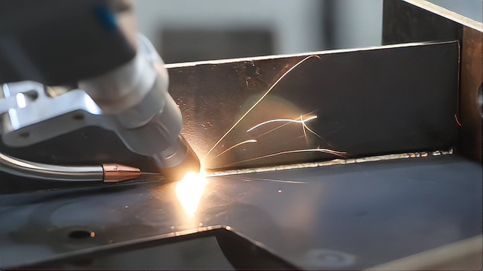
Wobble laser welding sweeps the focused beam through a small repeating pattern while the part or the optics travel along the joint. The technique exists to solve a production problem: a sharply focused laser is unforgiving of gaps, contamination and vapor entrapment, and many shops cannot hold the fit that such a focus demands. Oscillating the beam widens the root, lengthens the life of the melt pool and stirs gas out before the metal freezes. This article covers the cases where that trade pays off, the parameters that control the result, and the situations where you should keep the beam stationary.
How Oscillation Changes the Weld Pool
A fixed focus concentrates power into a narrow keyhole, which gives deep penetration and a steep thermal gradient. Once the beam is oscillated, the effective working diameter becomes roughly the oscillation amplitude plus the focused spot. Power density falls, the pool grows wider and shallower, and it stays liquid longer. Because the pool lives longer, hydrogen and zinc vapor have more time to escape, and the grain structure shifts from long columnar toward something closer to equiaxed. Both effects reduce porosity and centerline cracking in aluminum and in coated steel. The price is penetration: at the same laser power, a wobbled weld in steel is often 20 to 40 percent shallower than a straight one, and the gap widens as amplitude and travel speed increase.
Patterns and How They Are Produced
The usual patterns are the circle, the figure eight, the infinity loop, the zigzag and the spiral. The circle is the default for thin sheet because it is symmetric and behaves identically in every travel direction. Figure eight and infinity patterns suit lap joints where a wide top and a narrower root are both wanted. The oscillation itself comes from one of three places. A galvanometer scan head flies the beam and reaches the highest frequencies, but it confines the working field to the scanner aperture, usually a few hundred millimeters. A motorized wobble module inside the process head covers a larger field at lower frequency. A few builders create the same motion through the robot or a rotary stage, which is inexpensive but slow and hard to keep in phase with the travel axis.
Where Wobble Earns Its Keep
Four situations justify the extra hardware and the programming effort. The first is a gap that varies along the joint, such as stamped or laser cut flanges with a loose tolerance stack. Oscillation widens the root and bridges openings that a sharp focus would leave unfused; as a common rule of thumb, thin steel parts with gaps up to about one third of the sheet thickness can often be joined, which means roughly 0.2 to 0.3 mm on 1 mm material, although the limit moves with amplitude and speed. The second is zinc coated steel, where the coating boils well below the melting point of the base metal. A wider, longer lived pool gives that vapor a path out instead of trapping it as porosity. The third is aluminum, where oscillation calms the violent spatter of a tight keyhole and reduces hot cracking. The fourth is lap welding with filler wire, where the wider pool improves wetting at the toe and produces a smoother transition into the parent metal.
Setting Amplitude, Frequency and Speed
Three values interact with travel speed, and they are best set in a fixed order. Start with amplitude. If amplitude is smaller than the focused spot, the beam barely moves relative to its own width and the effect is negligible; typical amplitudes for a 50 to 100 micrometer spot at 1 to 3 kW fall between 0.3 and 1.2 mm. Then set frequency so the distance travelled in one cycle stays a fraction of the amplitude. At 80 mm per second and 150 Hz the beam advances about 0.53 mm per cycle, which pairs well with an amplitude near 0.8 mm because consecutive sweeps overlap generously. Frequencies from about 50 to 300 Hz cover most thin sheet work. Finally, raise the power to recover the penetration lost to the wider pool, then confirm that the scan head can actually follow the command at that combination, because mirror inertia distorts the pattern long before the controller reports a fault.
Where Wobble Hurts
Oscillation is not a universal upgrade. Full penetration welds in thick section lose more depth than they gain in tolerance, and the power needed to compensate may exceed what the delivery optics can handle. Hermetic seals on small components favor a stable, stationary keyhole, since the wider pool raises total heat input and distortion. Close fitting parts with consistent, tight gaps gain nothing and simply run slower. Deep aluminum and copper welds that already depend on a high brightness source for penetration are usually run with a small circular motion only, if any at all. Tooling is also part of the decision: a scanner based cell needs a fixed working distance and a flat field, so a joint on a curved or poorly supported part may rule out the approach before the metallurgy is even considered.
A sensible way to adopt the process is to establish a baseline first. Weld the real production joint with a stationary beam and record penetration, gap tolerance and porosity, then add oscillation. Increase amplitude in two or three steps while holding speed constant, measure again, and keep the smallest amplitude that solves the gap or porosity problem. Wobble is a tolerance tool, so treat it as a late adjustment rather than the first one.
Comments (0)
No comments yet.
Sign in to join the discussion.