Laser Welding Copper and Aluminum for EV Battery Packs
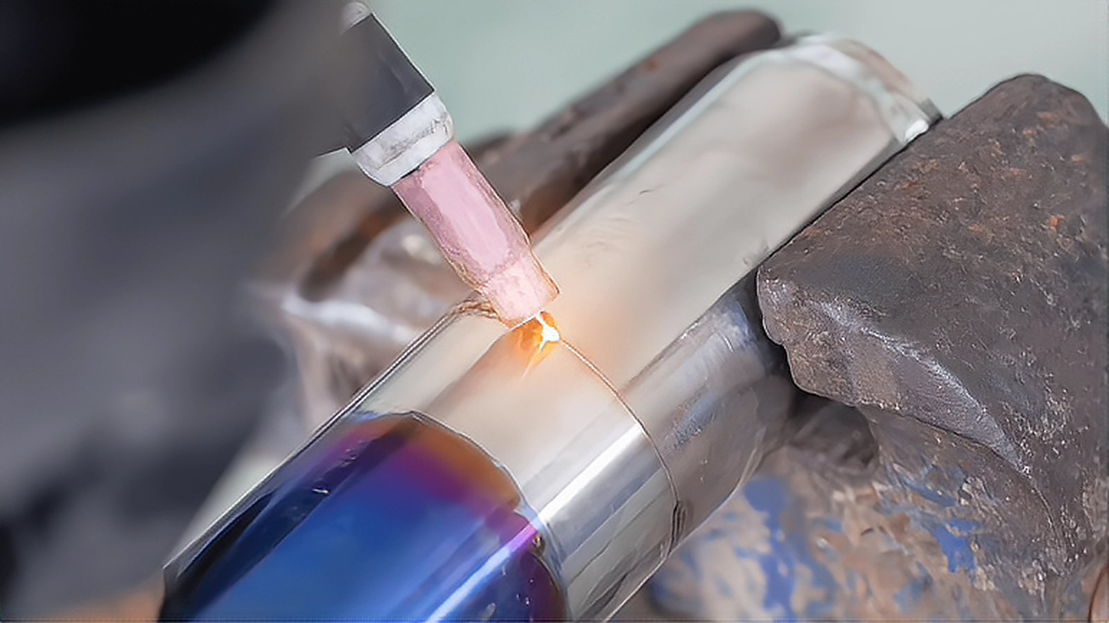
Copper laser welding sets the pace of a battery pack line, because busbars, foil tabs and motor hairpins are the joints that most often force a rework loop. Copper reflects most of the near infrared light that a common fiber laser delivers, and it conducts heat away roughly eight times faster than steel, so a keyhole is hard to start and easy to lose. This article explains how to get a stable copper weld with infrared sources and with blue or green ones, what aluminum adds when both metals appear in the same pack, and which checks catch a bad joint before the pack ships.
Why Copper Resists the Near Infrared
A copper surface absorbs poorly until it melts, and then absorption climbs sharply once a keyhole opens. That step change, not simple inefficiency, is what makes the process unstable: the beam couples weakly, then couples suddenly, and the transition throws spatter and can drive a spike of vapor through the root. Copper also oxidizes quickly in shop air, and the oxide changes absorption from batch to batch, so a recipe proven on one coil can behave differently on the next. Brightness matters more than raw wattage here. A single mode source focused into a 50 to 80 micrometer spot reaches the power density needed to force a keyhole, while a multimode beam of the same power spread over 300 micrometers may only heat the surface and reflect.
Blue and Green Sources
Blue diode lasers near 450 nm and green sources near 515 nm absorb far better in copper than infrared does, roughly an order of magnitude better at room temperature, and the advantage is largest at low power where infrared struggles to start a keyhole at all. The result is a wider, calmer pool, less spatter and more tolerance to surface condition and to small gaps. The trade is spot size and cost. Blue systems typically offer a few hundred micrometers of spot at 1 to 2 kW, so the weld is wide and shallow compared with a single mode infrared weld of equal power. Blue therefore fits thin foil stacks, tab to busbar joints and light gauge busbars, while infrared remains the choice when deep penetration in thick copper is required. Many cells run both, which means two process qualifications, two spare parts strategies and two sets of optical safety measures.
Aluminum in the Same Pack
Aluminum brings a second set of problems. It is reflective as well, its oxide melts far above the melting point of the metal, and it dissolves hydrogen readily, so porosity appears when the pool is dirty or too cold. Helium rich shielding mixtures increase penetration compared with pure argon, and cleaning before welding influences the outcome more than any single parameter change. Where a busbar transitions from copper to aluminum, the interface forms brittle intermetallic phases, and the practical response is to place that transition away from vibration and flexing, to design the joint in shear rather than in peel, and to qualify it with resistance measurements and mechanical testing instead of a visual check.
Foil Stacks and Fixturing
Foil stacks are the hardest geometry in a pack. Between 20 and 100 layers of very thin foil must be fused into one solid tab, and any gap between layers both blocks heat flow and traps gas. Clamping pressure, a machined backing bar and a flat anvil therefore matter as much as the laser recipe. Oscillating the beam spreads energy across the tab and reduces the chance of blowing through the upper layers, and the result is judged by cross section and by resistance across the tab rather than by bead appearance. Copper fume is a regulated workplace exposure, so local extraction at the weld and verified airflow belong in the same commissioning checklist as the process parameters; the general welding requirements are set out in the OSHA welding standard at https://www.osha.gov/laws-regs/regulations/standardnumber/1910/1910.252 .
Process Windows and Verification
When a copper weld spatters, the first adjustment is usually travel speed rather than power, because the keyhole needs a stable front wall to close behind the beam. When it shows porosity, look at surface condition and at shielding coverage before changing the recipe, since contamination and turbulent gas cause more defects than a modest shift in power. When the weld is simply too shallow, raise brightness rather than wattage: a smaller spot at the same power often penetrates more than a larger spot at double the power. Wobble amplitude and frequency then fine tune the width of the fusion zone and the amount of spatter, and they should be set only after the spot size and speed are settled.
Copper joints also fail in ways that are hard to see, so a pack line needs more than visual inspection. Cross sections at the start of a shift confirm penetration and porosity, resistance measurements on every tab catch the partial welds that look acceptable, and pull or peel tests at a defined frequency track the process drift. Inline monitoring adds value when it is tied to a documented action: a rise in spatter or a drop in keyhole depth signal should trigger a hold and a cross section, not just a data point. Record the laser serial number, the optics hours and the shielding gas flow with each weld, because a drifting focus lens changes the result long before it fails outright.
Start with one joint family and one geometry, and characterize it fully before scaling. Confirm the spot size and the brightness of the source, fix the shielding gas and the extraction, then move speed and power together in small steps while tracking penetration and spatter. Add inline monitoring only after the window is understood, and use it to detect departure from that window rather than to define it.
Comments (0)
No comments yet.
Sign in to join the discussion.