Lack of Fusion in Laser Welding: Why It Hides and How to Correct It
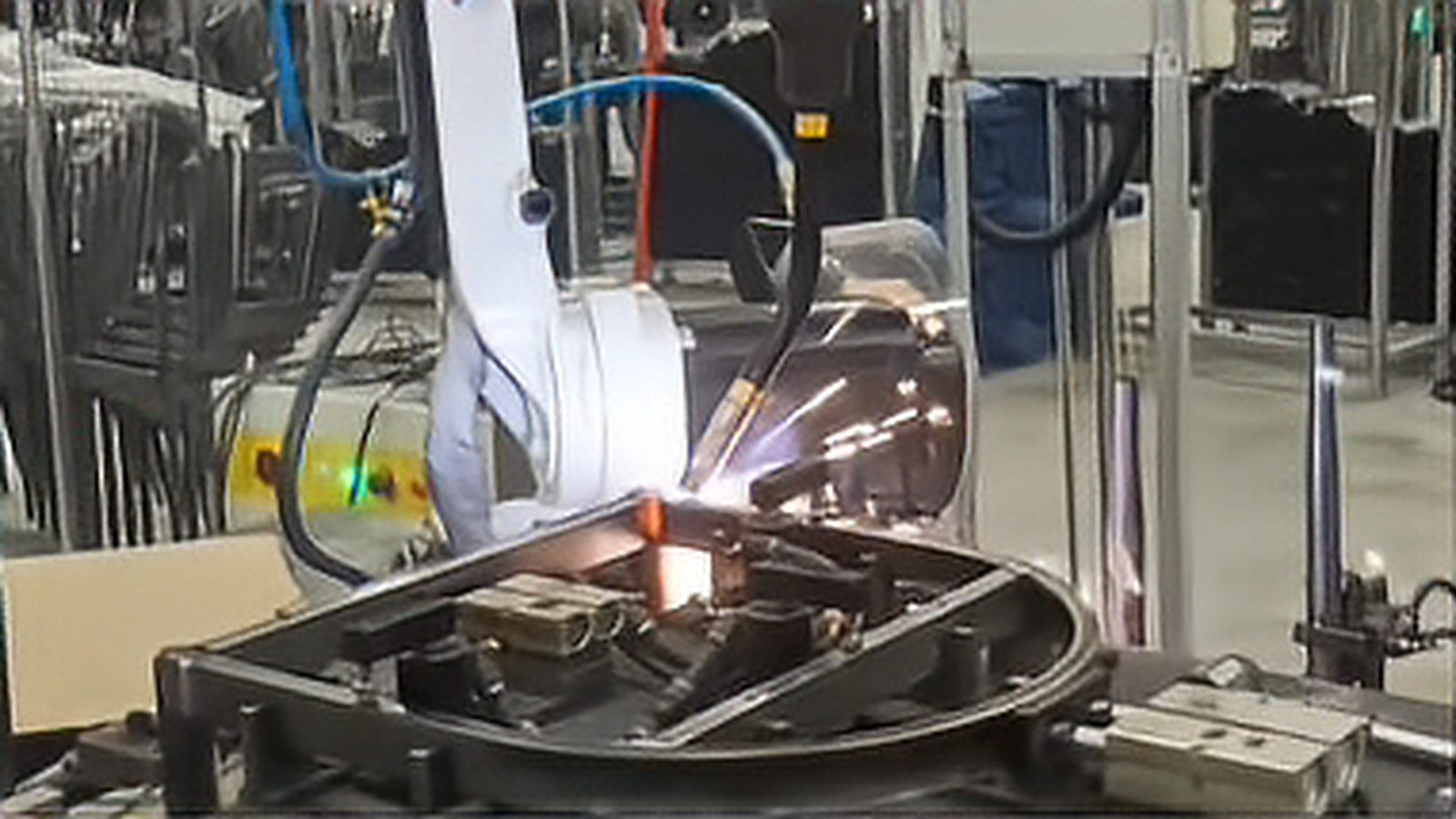
Lack of fusion is the most dangerous defect in laser welding because it gives almost no warning. A weld with an internal gap between the weld metal and the joint wall can look normal and then fail suddenly in service. Where spatter and undercut announce themselves, lack of fusion hides. This article explains how it differs from incomplete penetration and why a cross-section is the confirmation you can trust.
Why it is the most dangerous defect
The surface of a laser weld says very little about what happened at the root or along the walls. A weld can have a full, smooth bead and still not have bonded to one of the faying surfaces. Because the defect is internal, it escapes visual inspection, and it can escape destructive testing too if the wrong section is taken. When it fails, the failure is sudden rather than progressive, because the unbonded area carries no load.
Two faults that are often confused
Separate lack of fusion from incomplete penetration, because the two have different fixes. Lack of fusion means the weld metal did not wet and bond to the joint wall, or to a previous pass, even where the weld reached full depth. Incomplete penetration means the keyhole never reached the root, so the weld is simply too shallow. A weld can reach full penetration and still carry lack of fusion on a sidewall.
Energy density and coupling
Lack of fusion often starts with energy density that is too low at the interface. If the beam is spread too widely, or the focus puts a large spot on the surface, the power density at the joint walls may not be enough to melt and wet them. Coupling matters too, because heavy oxide, scale, or contamination reflect energy instead of absorbing it, so a setting that suited clean stock delivers less usable heat here. Confirm the power density at the joint with this guide to laser welding parameters.
Fit-up, gap and oxide
Gap is a direct cause of lack of fusion, because it changes how heat moves through the joint. When the parts do not sit in contact, heat is conducted away from the interface, the walls never reach bonding temperature, and the weld sits over a cold, unbonded gap. Oxide films are the second common cause. Aluminium is the classic example, because its surface oxide melts far above the metal beneath it and blocks wetting. The joint has to be both closed and clean.
Keyhole stability on deep narrow welds
A deep, narrow weld can be efficient and still unreliable. As the weld gets deeper relative to its width, the keyhole becomes a tall, thin channel that is harder to keep open, raising the risk of root discontinuities and pockets that never bond. On thicker material the channel deepens, so a small wobble in the keyhole matters more and the stable window narrows, as the wider picture of welding defects shows.
Quality level, test technique and acceptance level
A frequent confusion is the assumption that one standard covers everything, and it does not. The beam-welding quality standards ISO 13919-1:2019 and ISO 13919-2:2021 set quality levels for imperfections but do not cover inspection methods. The radiographic testing standards ISO 17636-1:2022, for film, and ISO 17636-2:2022, for digital detectors, describe the techniques but contain no acceptance levels. Those come from a separate family, such as ISO 10675-1:2021, while ISO 17635:2025 links quality levels to testing levels.
What radiography can and cannot see
Radiography is often the first method people reach for, and it has real limits. It is good at volumetric flaws such as voids and inclusions. It is much weaker at a tight, planar interface such as lack of fusion between two walls, because a thin unbonded plane may barely change the density in the beam path. Detection also depends on the angle of the source, so a fusion flaw can be invisible in one exposure and obvious in another.
What ultrasonic testing adds and where it stops
Ultrasonic testing is generally better than radiography at planar flaws, because the sound reflects from an unbonded interface rather than passing through it. The catch is scope and access. ISO 17640:2018, the technique standard for ultrasonic testing of welds, is written mainly for fully penetrated ferritic steel welds about 8 mm thick and above, and its acceptance levels are given in ISO 11666:2018. Thin laser welds often fall outside that range.
The cross-section as the reference
For all the value of non-destructive methods, the cross-section remains the reference. A section cut from the production joint, mounted, polished, and etched, shows whether the weld metal bonded to each wall and how far it penetrated. In-process monitoring can watch signals that correlate with instability and catch drift between inspections, but it measures the process rather than the joint, so it does not replace the section.
Corrective order and qualifying the process
When lack of fusion appears, resist the urge to add power first. Confirm the focus position and that the beam is centred on the joint, because an off-centre or poorly focused beam is a common cause and cheap to check. If the beam is correct, reduce travel speed in steps of about 10 to 20 percent to increase heat input and dwell time, which improves wetting. Only then raise power, in small steps. Remember that a process qualified on a sample is not automatically in control on the line, and ISO 15614-11:2025 covers the relevant welding procedure test.
Treat lack of fusion as the default assumption until you have evidence otherwise. If you have not looked at a cross-section of the joint in question, you do not know that it is bonded, however good the crown looks. Build sectioning into production, keep the sections with the parameters that produced them, and follow the focus-first correction order, as this guide to specifying a laser welding cell sets out. The broader family of welding problems rewards the same caution.
Sources and references
- ISO 13919-1:2019 Electron and laser-beam welded joints - Quality levels for imperfections - Part 1: Steel, nickel, titanium and their alloys - defines the beam-weld quality levels that are quoted when judging lack of fusion View source
- ISO 6520-1:2007 Welding and allied processes - Classification of geometric imperfections in metallic materials - Part 1: Fusion welding - provides the classification that separates lack of fusion from incomplete penetration View source
- ISO 17635:2025 Non-destructive testing of welds - General rules for metallic materials - links quality levels to testing levels and guides which method to select View source
- ISO 17636-1:2022 Non-destructive testing of welds - Radiographic testing - Part 1: X- and gamma-ray techniques with film - sets the technique for film radiography but no acceptance levels View source
- ISO 17640:2018 Non-destructive testing of welds - Ultrasonic testing - Techniques, testing levels, and assessment - covers ultrasonic technique mainly for fully penetrated ferritic steel welds from about 8 mm thick View source
- ISO 10675-1:2021 Non-destructive testing of welds - Acceptance levels for radiographic testing - Part 1: Steel, nickel, titanium and their alloys - supplies the radiographic acceptance levels that the technique standards do not View source
Comments (0)
No comments yet.
Sign in to join the discussion.