How to Read a Weld Bead: A Visual Guide to Weld Quality
A weld bead is the cheapest inspection report you will ever get. Before you spend money on X-ray, ultrasonic testing or tensile coupons, the bead surface itself records what happened in the melt pool: how fast the beam traveled, how much power it delivered, whether the shielding gas did its job, and whether the keyhole stayed stable. Learning to read a weld bead turns a five-second glance into a process diagnosis — and on a production floor, that is the difference between a contained deviation and a scrapped batch.
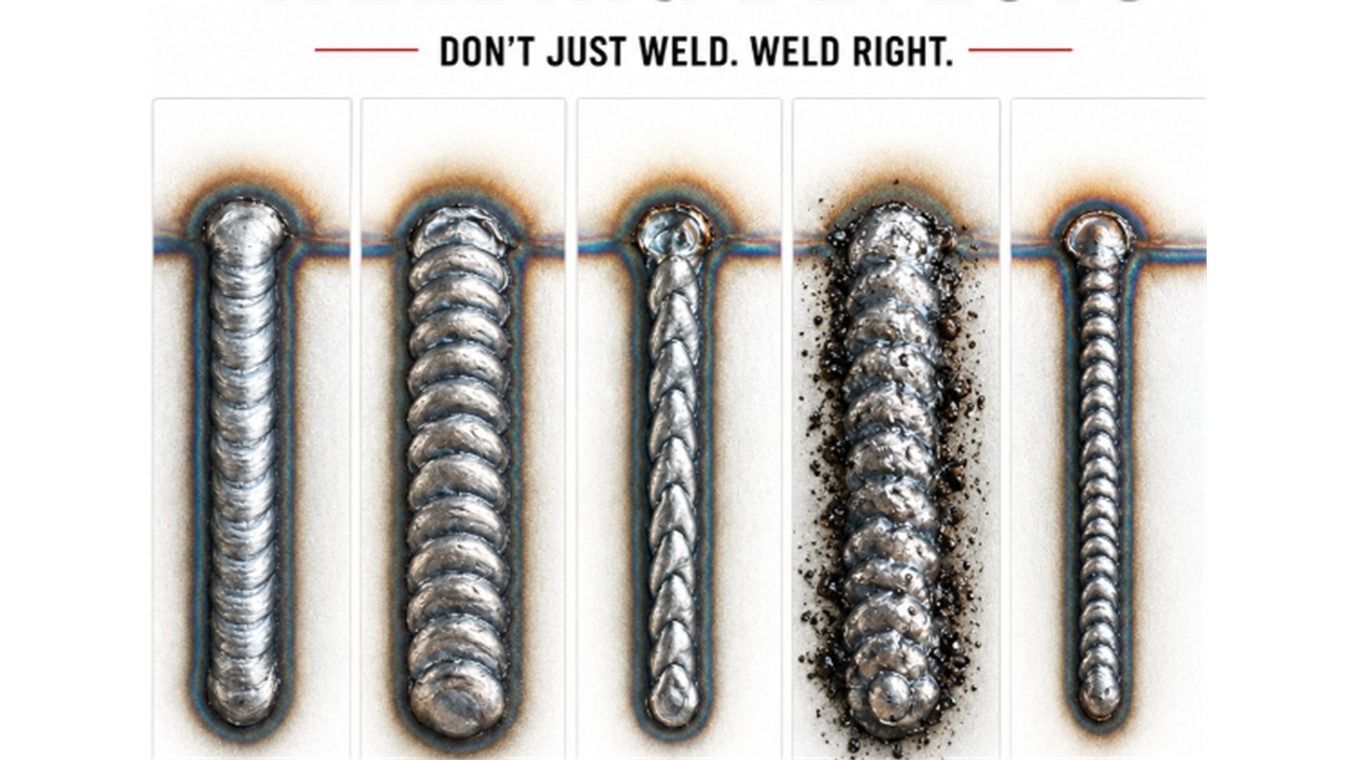
Five beads from the same joint design, welded with different parameter sets. Each one is a fingerprint of a different process state.
Why the Bead Surface Is a Process Record
During laser welding the melt pool solidifies almost instantly behind the moving keyhole — cooling rates in the range of 10^4–10^6 K/s are typical for fiber lasers on steel and aluminium. Whatever the fluid was doing in the last milliseconds before solidification is frozen into the surface geometry: ripple shape, width, height, oxidation colour and spatter distribution.
That is why two welds that pass a visual "looks fine" check can behave completely differently under load. The bead does not lie, but you have to know which features to look for and, more importantly, which parameter each feature points back to.
What the Ripples Tell You
Ripples are the oscillation marks left as molten metal flows around the keyhole and refills it. Their two measurable properties — spacing (pitch) and shape — carry distinct information.
- Fine, evenly spaced ripples indicate a stable keyhole with consistent melt pool flow. Ripple pitch is essentially travel speed divided by melt pool oscillation frequency; steady pitch means steady speed.
- Wide, chunky scallops (each scale mark large and pronounced) usually mean the beam moved slowly relative to the power being delivered. More melt is being deposited per unit length, and heat input climbs with it.
- Irregular or changing pitch along the joint is a warning sign: speed fluctuation, joint gap variation, or a melt pool transitioning between conduction and keyhole regimes.
- A twisted or braided pattern, where the bead zig-zags instead of running straight, points to beam oscillation that is too wide for the joint, poor fit-up the beam is chasing, or directional gas flow disturbing the pool.
Ripple quality is also a fusion indicator: well-blended ripples that fade smoothly into the fusion line at the bead edge suggest the walls of the groove were properly wetted. Sharp, unfused edges between ripple valleys and the base metal are an early sign of lack of fusion.
Bead Width: Your Proxy for Penetration
On a square butt joint you cannot see penetration depth without sectioning — but bead width correlates with it, because both scale with the energy delivered into the keyhole. A practical rule used on shop floors:
| Bead width vs. expectation | Likely penetration | Typical cause |
|---|---|---|
| Noticeably wider than reference coupon | Deeper than expected, wide HAZ | Power too high, speed too low, defocus too small |
| Matches qualified reference | On target | Process at setpoint |
| Narrower than reference | Shallower; risk of partial penetration | Speed too high, power too low, beam misalignment |
The critical caveat: width only predicts penetration when the joint geometry, fit-up and material condition are constant. A narrow bead over a tight gap can be fully penetrated; the same narrow bead bridging a 0.2 mm gap may be a lack-of-fusion defect waiting to open under load. Always qualify a reference window, then judge production beads against it rather than against absolutes.
Reinforcement, Underfill and Concavity
The bead's cross-sectional profile matters as much as its top view:
- Excessive reinforcement (a tall, convex bead) wastes filler-free deposition energy and creates a stiff geometric discontinuity at the toe — a fatigue stress riser.
- Underfill or concavity (a saddle-shaped bead dipping below the surface) is worse: the centerline sits in tension and the toes act as notches. On dynamically loaded parts, a concave bead is frequently the crack initiation site even when the weld is otherwise sound.
- A slightly convex bead with smooth toe blend is the target for most production laser welds — it says the melt pool had enough volume and time to wet the fusion line before freezing.
HAZ Colour: The Shielding Gas Story
The discoloured band around the bead is the heat-affected zone, and its colour is an oxidation thermometer. On stainless steel, a pale straw to light grey band means the gas shield kept temperatures below the oxidation threshold. Deep blue, purple, grey-black or "sugary" oxide on the bead crown means oxygen reached molten metal — either the backing side had no purge, the nozzle stood too far from the joint, or the flow rate was wrong.
Oxidation is not only cosmetic. Oxide films on aluminium and steel change surface tension gradients (Marangoni flow), destabilise the keyhole, and increase susceptibility to porosity. If you see heavy discolouration, check gas purity, nozzle distance and coverage before touching power or speed — and see our comparison of argon, helium and nitrogen for fiber laser welding for how gas choice shapes the bead.
Spatter: Symptom of an Unstable Process
Spatter — the ejecta field around a bead — is the most visually obvious defect, and the one most often misdiagnosed as "just messy." In laser welding, spatter forms when the keyhole or melt pool ejects material: too much power density for the speed, a keyhole that collapses and pinches off vapour jets, an underfilled groove causing the beam to strike bare metal, or gas blowing directly into the plume.
A bead with spatter almost always has a companion defect: the ejection removed melt that should have gone into the bead, leaving underfill, micro-voids or an irregular fusion line. Treat visible spatter as a process instability alarm, not a cosmetic issue.
Reading the Five Beads
Putting it together on the comparison image above, the five beads illustrate a full diagnostic spectrum:
- Smooth, narrow bead with fine uniform ripples — the balanced reference. Stable keyhole, correct speed-to-power ratio, good gas coverage.
- Wide bead with large scallops — over-deposited: travel speed too low or power too high for the joint. Sound-looking, but high heat input and a wide HAZ.
- Thin, twisted bead — directional instability: oscillation amplitude mismatched to the joint, fit-up wander, or gas interference.
- Bead buried in spatter — the process is running beyond its stability window; expect hidden porosity and underfill beneath the ejecta.
- Very narrow, sharply defined bead — under-penetrated or barely wetting the fusion line; a lack-of-fusion risk despite its tidy appearance.
The lesson the image makes visually: the two "prettiest" beads (#1 and #5) sit at opposite ends of the quality spectrum, and the ugliest bead (#4) is telling you the least subtle truth. Appearance must always be interpreted against a qualified parameter window.
Troubleshooting Matrix
| What you see on the bead | Most likely root cause | First parameter to check |
|---|---|---|
| Wide scalloped ripples, large HAZ | Low travel speed / high heat input | Travel speed, then power |
| Narrow bead, sharp unfused edges | Insufficient energy or misalignment | Defocus and beam centring |
| Spatter field around bead | Keyhole instability, over-power | Power density; peak vs. CW mode |
| Blue/black oxide, sugary top | Shielding gas failure | Nozzle distance, flow rate, purge |
| Zig-zag or wandering bead | Oscillation/joint mismatch, fit-up | Weave width vs. gap; fixture rigidity |
| Porosity-like pinholes at crest | Trapped vapour from contamination | Surface cleanliness, gas purity |
If your process swings between conduction and keyhole regimes, mode choice matters as much as average power — our guide to pulsed vs. continuous-wave laser welding explains how pulse shaping stabilises the pool on thin material, where bead reading is hardest.
Why Robotics Changes the Interpretation Game
Manual welders produce beads that mix process state with operator variation — the same defect can mean two different things depending on who held the torch. A robot removes that variable: travel speed, standoff and oscillation are constant, so a bead that changes from part to part is almost always telling you the process drifted (laser power decay, lens contamination, fixture shift), not the welder.
That consistency is what makes bead reading quantitative rather than qualitative, and it is the foundation for closed-loop quality: automated inspection methods for laser welds pair easily with robotic cells because the reference window is narrow and repeatable.
From Inspection to Closed Loop
The mature end-state of bead reading is not a human with a magnifying glass — it is a calibrated process window. Photograph reference beads at the edges of your qualified parameter set, document what each looks like, and train inspectors (or vision systems) to classify production beads against that library. When the bead is no longer a mystery but a measured feature, your first line of quality control costs nothing.
FAQ
What does a good laser weld bead look like? Fine, evenly spaced ripples blending smoothly into the fusion line; width matching the qualified reference; slight convexity with no undercut; minimal discolouration and no spatter field.
What causes spatter in laser welding? Excessive power density for the travel speed, keyhole collapse ejecting melt, an open root gap the beam strikes directly, or shielding gas disrupting the vapour plume. It signals process instability, not just mess.
Does bead width indicate penetration depth? It correlates, because both scale with energy input into the keyhole — but only against a qualified reference at constant joint geometry and fit-up. Use width to detect deviation, not to certify depth.
Why is my weld bead concave and is it a problem? Concavity usually comes from too-high speed or too-low power for the joint, or from gravity on overhead positions. It is a problem under dynamic load: the dipped centerline and sharp toes act as a notch and fatigue initiator.
Want to build a qualified bead library for your cell? Contact WeldProBot to talk through parameter development and robotic process monitoring.
Comments (0)
No comments yet.
Sign in to join the discussion.