Keyhole Laser Welding Explained: Beam, Plume, Gas and Pool
Key takeaways
- The mode switch. Keyhole welding begins when focused intensity is high enough to vaporize metal. Published sources place the switch anywhere between roughly 10⁵ and 10⁷ W/cm², and one controlled study found no single value, because the threshold shifts with beam diameter and interaction time [1][2][3].
- Absorption jumps. Once a keyhole forms, the beam is trapped by multiple reflections. Older data show aluminum absorbing about 2% of 10.6 µm light on a flat surface and 60% or more once keyholing starts [17]. Well-formed keyholes can exceed 90% absorption [4].
- The plume matters differently for each laser. Inverse bremsstrahlung absorption scales with the square of the wavelength, so a 1 µm fiber laser loses roughly 100 times less energy to plasma than a 10.6 µm CO₂ laser [10]. One test on 304 stainless steel measured only about 4% probe-beam attenuation, and the authors attributed it mainly to something other than plasma absorption [11].
- Porosity and spatter are keyhole-stability problems. X-ray imaging shows keyhole depth can fluctuate by about 40% even with a continuous beam [8], and spatter becomes a serious problem above roughly 8 m/min with solid-state lasers [16].
- Shielding gas does more than stop oxidation. It changes plume behavior and keyhole stability, and the effect depends on laser wavelength and material [12][13][20].
If you have watched a high-speed recording of a laser weld, you know the process is anything but a calm bead being laid down. A narrow cavity of metal vapor opens in the melt, flickers, collapses, reopens, and throws droplets out of its mouth, all in milliseconds. Almost every defect we cover on this site, from porosity to spatter to burn-through, traces back to what happens inside and around that cavity. This article walks through one schematic of a keyhole weld, element by element, and attaches published measurements to each part.
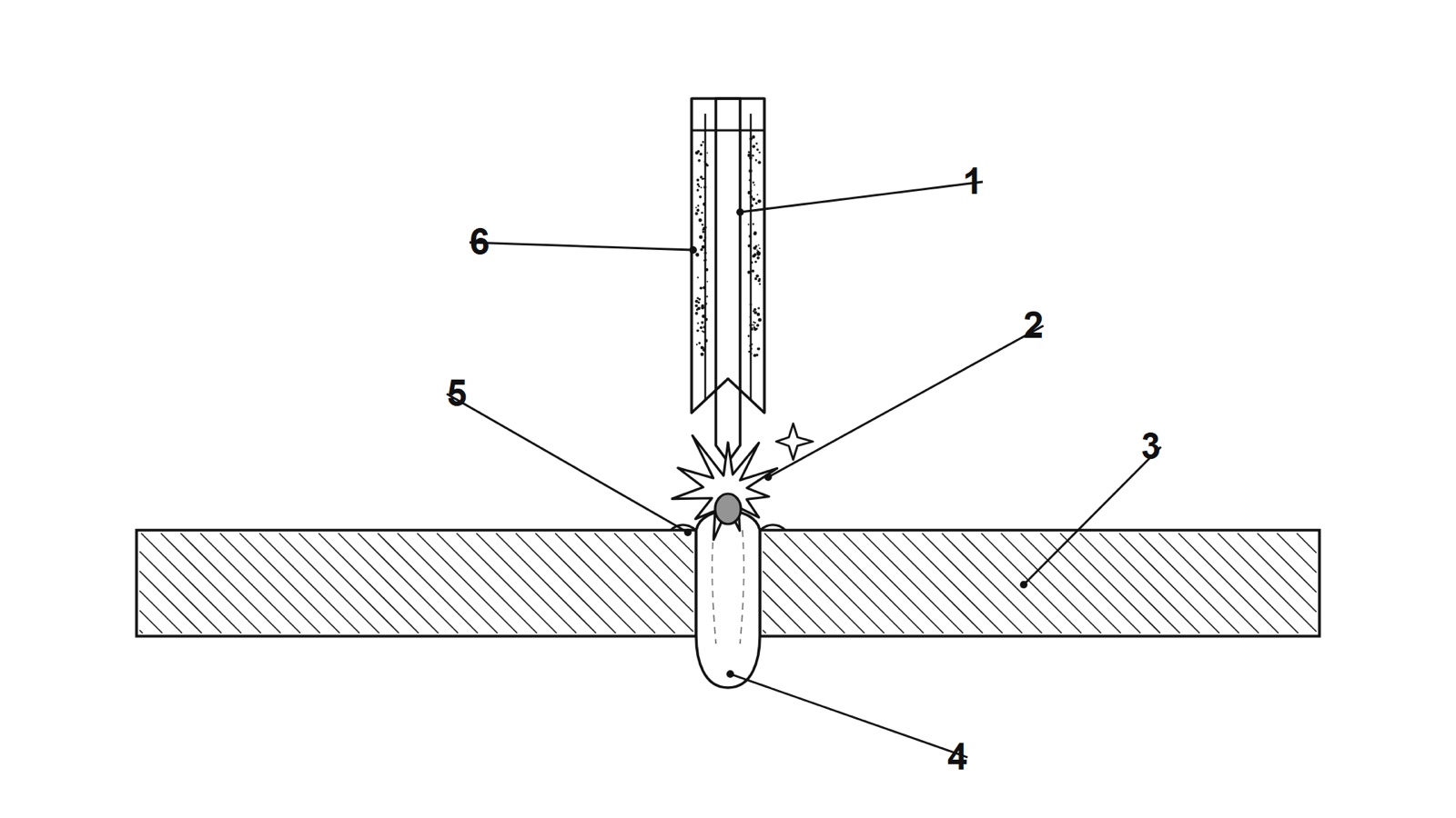
1. Reading Figure 1: six elements of a keyhole weld
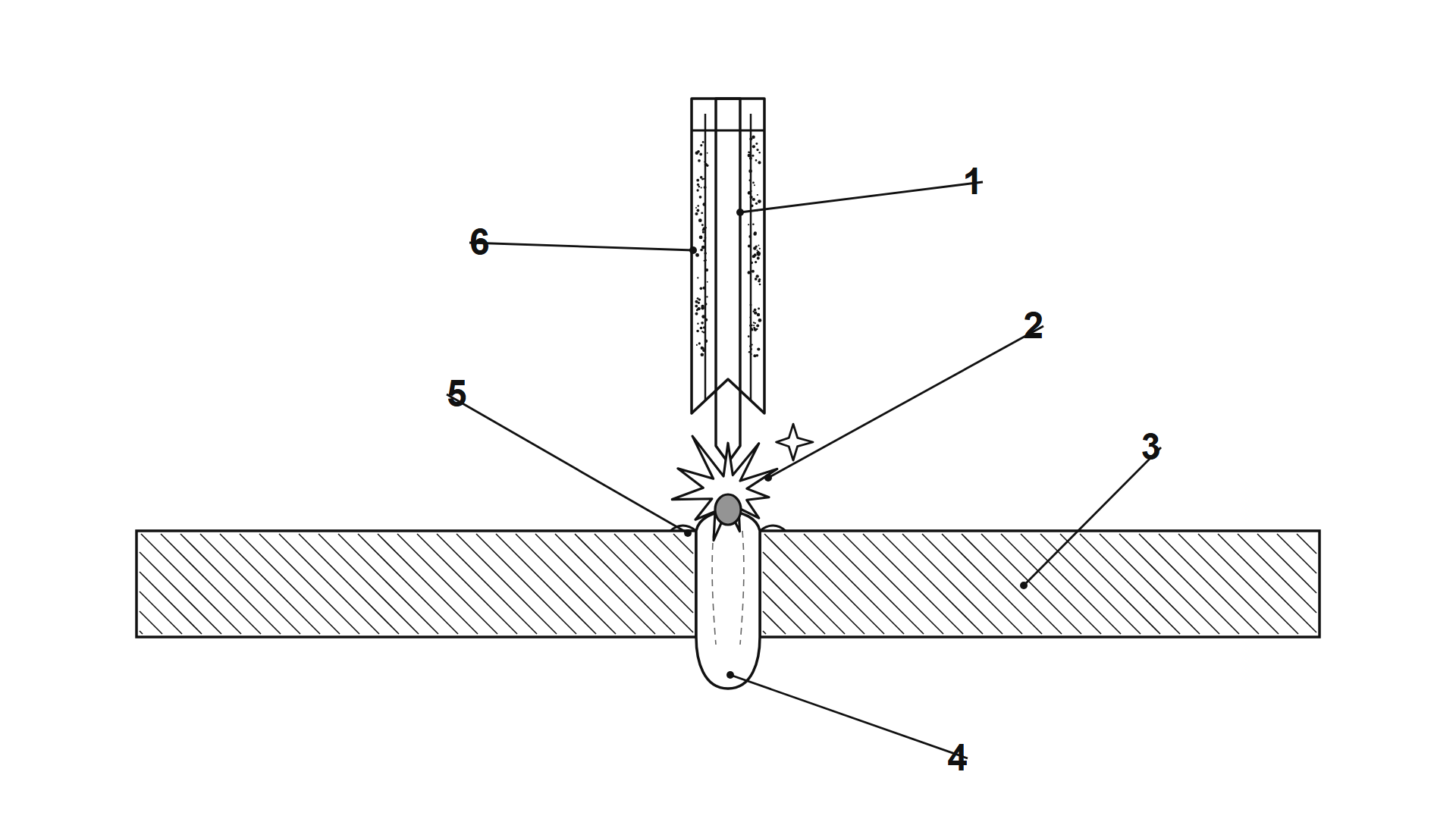
| Label | Element | What it does | Main process controls |
|---|---|---|---|
| 1 | Focused laser beam | Delivers the power; intensity at the surface decides conduction or keyhole mode | Power, spot diameter, focal position, beam quality |
| 2 | Metal-vapor and plasma plume | Vapor leaving the keyhole mouth, partly ionized; can scatter or absorb the beam | Wavelength, gas type and flow, nozzle position |
| 3 | Workpiece | Absorbs energy; reflectivity, coatings and joint gap change the result | Material, surface condition, fit-up |
| 4 | Keyhole and melt pool | Vapor-filled cavity surrounded by liquid metal; its stability sets weld quality | Welding speed, power density, focus |
| 5 | Spatter | Melt droplets ejected near the keyhole rim | Speed, keyhole stability, gas flow, beam shape |
| 6 | Shielding gas flow | Protects the weld and shapes plume behavior | Gas type, flow rate, nozzle geometry |
Two simplifications in the drawing are worth remembering. First, a real keyhole is not a straight vertical tube. At higher speeds it tilts backward and the laser is absorbed mostly on its front wall [16]. Second, the drawing shows a through-thickness (full-penetration) keyhole. Partial-penetration welds have a blind keyhole, and vapor can only leave through the top opening.
2. From conduction to keyhole: the intensity threshold
Laser welding runs in two regimes. In conduction mode the surface melts but does not boil, and heat spreads inward by conduction alone, producing wide, shallow welds. In keyhole mode the beam vaporizes metal, and recoil pressure from that vapor pushes a deep, narrow cavity into the melt [1].
TWI states that conduction welding typically occurs below about 10⁵ W/cm², while keyhole welding typically needs more than 10⁶ to 10⁷ W/cm² [1]. A study of absorption measurements places the transition at 1 to 2 × 10⁶ W/cm², and reports that the depth-to-width ratio used to separate the two modes is typically drawn between 0.8 and 1.0 [3]. Amada Weld Tech describes a transition mode near 1 MW/cm² (10⁶ W/cm²) and gives 0.05 to 0.3 mm as the usual focused spot size for continuous-wave welding [5].
The spread in these numbers is not sloppy science. A Cranfield University study varied beam diameter and interaction time and concluded that the conduction-to-keyhole transition is not defined by a single power density; it is a range that depends on both [2]. Treat 10⁶ W/cm² as a working rule of thumb, not a switch.
| Feature | Conduction mode | Keyhole mode |
|---|---|---|
| Typical intensity | Below about 10⁵ W/cm² [1] | Above about 10⁶ to 10⁷ W/cm² [1] |
| Energy coupling | Surface absorption, then heat conduction | Absorption inside a vapor cavity |
| Weld shape | Wide and shallow | Narrow and deep |
| Stability | Stable, few defects | Sensitive to speed, focus and gas; pores and spatter possible |
A worked example: why spot size is the lever
For an idealized circular, uniform spot, power density is Pd = 4P / (π d²) [19]. The table applies this formula to a 4 kW beam. These values are our own calculations, and real beams have non-uniform profiles with higher peak intensity, so treat them as averages.
| Spot diameter | Spot area | Average power density at 4 kW | Likely regime |
|---|---|---|---|
| 0.2 mm | 0.031 mm² | 1.3 × 10⁷ W/cm² | Keyhole |
| 0.3 mm | 0.071 mm² | 5.7 × 10⁶ W/cm² | Keyhole |
| 0.6 mm | 0.283 mm² | 1.4 × 10⁶ W/cm² | Keyhole, close to the transition |
| 1.0 mm | 0.785 mm² | 5.1 × 10⁵ W/cm² | Transition zone, conduction-like |
The same 4 kW moves from deep keyhole welding to the edge of conduction mode just by enlarging the spot from 0.3 mm to 1.0 mm. Measured data agree on the order of magnitude: TWI calculated beam-waist power density for 4 kW at the workpiece across four laser types and focusing conditions, and the results ran from 13.7 to 264.4 kW/mm² (about 1.4 × 10⁶ to 2.6 × 10⁷ W/cm²) [7]. At the extreme end, a 10 kW fiber laser focused to about 100 µm reaches the 1 MW/mm² class [11].
Focus size itself follows a simple relationship: fiber diameter multiplied by focal length and divided by collimation length [6]. The same source notes that typical spot sizes for butt welding range from 50 to 900 µm, and that joint position tolerance must stay below half the beam diameter so the beam meets both sides of the joint [6]. We return to that point in the troubleshooting section.
For more on this relationship, see our guide Spot Size and Power Density in Laser Welding.
3. Inside the keyhole (labels 1, 3 and 4): why absorption jumps
A flat metal surface reflects much of an infrared laser beam. A keyhole changes that. The beam enters a deep cavity and bounces between its walls, and each bounce deposits a fraction of the energy, so the total absorbed can be far higher than on the flat surface [4].
- Aluminum has an initial absorptivity of about 2% at 10.6 µm, but keyholing raises the absorbed share to 60% or more, according to a classic review in the Indian Welding Journal [17].
- A 2024 Welding in the World study notes that multiple reflections inside a keyhole considerably raise overall absorption, and that efficiencies above 90% can be reached even when single-reflection (Fresnel) absorption is low [4].
- The same study measured room-temperature absorption in nickel rising from about 30% at 1030 nm to about 50% at 445 nm, which is why blue lasers are attractive for conduction-mode welding of copper and nickel [4].
- For full-penetration welds, a 2026 modeling study reports that at low and moderate speeds (up to 6 m/min) the entire incident beam enters the capillary. At higher speeds part of the beam hits the sheet ahead of the keyhole [18].
This is why a keyhole weld is so efficient, and also why it is touchy. Absorption depends on the cavity shape, and the cavity shape is constantly changing.
4. The plume (label 2): when does it matter?
Metal vapor leaving the keyhole mixes with the surrounding gas and forms a plume above the weld. How much that plume interferes with the beam depends on the laser wavelength.
CO₂ lasers (10.6 µm). Inverse bremsstrahlung absorption, where free electrons in the plasma absorb laser light, grows with the square of the wavelength. At 10.6 µm the plume can absorb and defocus enough of the beam to cut penetration sharply, which is why helium, with its high ionization potential, became the standard shielding gas for high-power CO₂ welding [12]. Argon ionizes more easily and can form a parasitic plasma in the gas above the weld at high CO₂ power; Air Liquide researchers presented a special nozzle that allowed argon at about 35 L/min with weld quality equal to helium [12].
Fiber and disk lasers (about 1 µm). At 1.07 µm the same absorption mechanism is about 100 times weaker, and the plume is a weakly ionized, relatively cold vapor at roughly 3000 to 6000 K rather than a hot plasma [10]. In a test on 20 mm thick 304 stainless steel with a 0.9 MW/mm² beam under 30 L/min of argon, a probe beam through the plume lost about 4%, and the authors attributed it mainly to something other than inverse bremsstrahlung [11]. A BAM dissertation record also reports that shielding gas (argon or helium) cools the lower part of the plume, up to complete suppression of its plasma [22].
There is a caveat. A spectroscopic study of fiber laser welding of aluminum alloys argues that plasma shielding should not be ignored once laser power reaches about 5 kW [26]. So for fiber lasers, the plume is usually a minor power loss, but at multi-kilowatt power on some alloys it is not negligible.
Even where the plume steals little power, it is still a useful diagnostic. High-speed imaging studies tie plume and keyhole dynamics together, for example a weakened plume during a vapor explosion at the back of the melt pool in full-penetration welding of titanium [15]. A plume that is bright, large and erratic often points to a keyhole that is not stable.
5. Shielding gas (label 6): more than an oxidation shield
The gas stream in Figure 1 protects the weld from air, but it also shapes the plume and influences the melt pool. The studies below show how much the choice matters.
| Gas | What the sources report | Practical note |
|---|---|---|
| Helium | High ionization potential suppresses shielding-gas plasma in high-power CO₂ welding [12] | Expensive; most relevant to CO₂ lasers |
| Argon | Easily ionized, which is a problem for high-power CO₂ welding [12]; widely used with fiber lasers, for example in the 30 L/min test above [11]. In a 304 stainless steel test at 5 kW and 2 m/min, argon gave an irregular keyhole front and some spatter [13] | Common default; check keyhole stability at your speed |
| Nitrogen | In the same 304 test, pure nitrogen gave a stable keyhole with no significant bubbles, and pores disappeared at higher nitrogen fractions [13] | Source is a preprint. Nitrogen changes weld-metal chemistry, so confirm it is allowed for your alloy and code |
Two more findings matter for process setup:
- Gas velocity changes the weld. In CO₂ welding, side-assist gas velocity significantly changed both the laser-induced plasma and the weld cross-section [20].
- Local gas flow can limit spatter, with limits. For solid-state lasers above 8 m/min, researchers tested local gas flow to curb spatter. It reduced spatter and pores in partial-penetration welds up to 5 m/min, but its effect on full-penetration welding at high speed was not yet clear [16].
In practice, gas settings that look fine on a slow trial weld can behave very differently at production speed, so test at the speed you will actually run.
6. The keyhole and melt pool (label 4): where porosity starts
The cavity in Figure 1 looks steady only because a drawing is a snapshot. X-ray transmission imaging of a 20 kW CO₂ laser weld deeper than 20 mm showed keyhole depth varying by about 40% even with a continuous beam [8]. Bubbles formed at the keyhole tip when the depth dropped abruptly and liquid metal closed the cavity just above the tip, a capillary instability of the narrow cylindrical keyhole. Most bubbles merged in the pool and survived solidification as porosity. Raising power density in the keyhole helped suppress porosity by stabilizing the cavity, but adjusting the parameters alone was not enough to prevent it in that study [8].
A 2025 paper in Science used high-speed X-ray imaging to show that a protrusion on the rear keyhole wall, driven by a flow vortex in the melt, is what initiates keyhole instability. Applying a magnetic field suppressed it [9]. That is research-stage, not shop-floor practice, but it confirms that the rear wall is where trouble begins.
Full penetration changes the vapor path but does not remove the risk. In full-penetration copper welding, hot vapor escapes through both the upper and lower openings [23]. In full-penetration titanium welding, high-power, high-speed conditions produced large, slow spatter from a liquid column breaking up on the keyhole wall, and excess vapor pressure caused an explosion on the back side of the pool [15].
For defect-specific fixes, see our guides Laser Welding Defects, Burn-Through in Laser Welding and Lack of Fusion in Laser Welding.
7. Spatter (label 5): what the research says
Spatter is the visible symptom of an unstable keyhole, and speed controls where and how it forms.
- Low speed. Recoil pressure from evaporation squeezes the molten layer on the front keyhole wall, producing spatter ahead of the keyhole mouth. Droplets were mostly 50 to 100 µm in diameter and flew faster [14].
- High speed. The front wall tilts further, vapor from it strikes the rear wall, and spatter appears behind the keyhole mouth. Droplets were mostly 100 to 150 µm [14].
- The 8 m/min line. With solid-state lasers, spatter becomes a major issue above about 8 m/min, and the dominant mechanism changes as keyhole inclination increases [16]. Fraunhofer ILT researchers working at 12 m/min on austenitic steel found that superimposed laser intensities reduced the melt flow energy around the keyhole and therefore the spatter [24].
- Beam shaping. In aluminum alloys, a hybrid fiber and semiconductor laser reduced spatter; the authors attribute spatter mainly to surface tension and recoil pressure, and credit the hybrid beam with a more uniform recoil pressure distribution [25].
Our article Laser Welding Spatter: Causes and Prevention covers fixes in more detail, and Wobble Welding: When Beam Oscillation Helps explains one way to calm the pool.
8. A troubleshooting matrix
The table below is editorial guidance that connects the research above to common symptoms. It is not a substitute for a qualified welding procedure.
| Symptom | Zones in Figure 1 | First checks | Evidence |
|---|---|---|---|
| Spherical pores | 4, 6 | Speed against power; focus position; gas type (for example nitrogen share where the alloy allows it) | [8][13] |
| Heavy spatter | 4, 5, 6 | Welding speed (especially above about 8 m/min); focus; local gas flow; beam shape | [14][16][24] |
| Shallow penetration despite enough power | 1, 2, 3 | Spot too large, so intensity falls toward the transition zone; focus offset; plume interference at high power | [2][7][26] |
| Burn-through | 1, 4 | Power density too high for thickness or speed too low | [8][15] |
| Lack of fusion or a missed joint | 1, 3 | Joint gap and position error against the half-beam-diameter rule | [6] |
9. Notes for robotic laser cells
In a robotic cell, the keyhole is at the mercy of the robot motion. These points follow from the evidence above, and are our own engineering reading rather than direct findings.
- Hold the speed at corners. Keyhole inclination and the spatter mechanism change with welding speed [14][16], so speed dips and spikes at corners change the process, not just the cycle time.
- Keep focus and tolerance repeatable. The half-beam-diameter positional tolerance [6] is tight for a 0.3 mm spot, which makes fixturing and seam tracking a quality issue, not a convenience.
- Qualify at production speed and gas settings. Gas effects reported above change with speed [16], so a slow teach-pass is not proof.
- Watch the optics. Spatter and vapor can contaminate protective windows, which reduces effective power at the workpiece. Add this to the preventive maintenance schedule.
10. Frequently asked questions
What power density do I need for keyhole laser welding? A common rule of thumb is about 10⁶ W/cm² or more, but the threshold depends on beam diameter, interaction time and material, and published values range from about 10⁵ to 10⁷ W/cm² [1][2][3].
Is the plasma plume a problem for fiber laser welding? Usually a minor one, because plume absorption at 1 µm is about 100 times weaker than at 10.6 µm [10]. It can still matter at multi-kilowatt power on some alloys [26], and it is a good indicator of keyhole stability.
Which shielding gas is best for laser welding? There is no universal answer. Helium suits high-power CO₂ welding, argon is the common default for fiber lasers, and nitrogen stabilized the keyhole in one 304 stainless steel test, though that source is a preprint and nitrogen alters weld chemistry [12][13].
Why does keyhole welding cause porosity? Because the keyhole fluctuates. Bubbles form when the cavity closes above its tip and are trapped by the advancing solidification front [8].
11. Limits of the evidence
The numbers above come from peer-reviewed papers, conference papers, institutional technical pages, patents and one preprint, across different lasers, alloys and thicknesses. Several are laboratory observations (X-ray imaging at synchrotron facilities, for instance) and may not transfer directly to your parts. Always qualify your procedure against the standard your customer specifies. ISO 13919-1 defines quality levels for imperfections in laser-beam-welded steel joints [27]; check the current edition before using it.
References
- TWI. What is Laser Welding and How Does it Work? https://www.twi-global.com/technical-knowledge/faqs/faq-how-does-laser-welding-work
- Assunção E., Williams S., Yapp D. Interaction time and beam diameter effects on the conduction mode limit. Optics and Lasers in Engineering 50(6), 823–828 (2012). doi:10.1016/j.optlaseng.2012.02.001
- Study on identifying the conduction and keyhole regimes by absorption measurement. International Journal of Advanced Manufacturing Technology (2023). doi:10.1007/s00170-023-11041-9
- Study of keyhole welding of nickel with infrared and blue laser wavelengths. Welding in the World (2024). doi:10.1007/s40194-024-01713-9
- Amada Weld Tech. Laser Welding Fundamentals (2016). https://www.amadaweldtech.eu/sites/default/files/documents/whitepapers/Laser%20Welding%20Fundamentals%202016.pdf
- The Fabricator. Essential considerations for laser welding. https://www.thefabricator.com/thefabricator/article/laserwelding/essential-considerations-for-laser-welding
- TWI. Spot Size, Laser Quality and Welding Performance. https://www.twi-global.com/technical-knowledge/published-papers/the-effect-of-spot-size-and-laser-beam-quality-on-welding-performance-when-using-high-power-continuous-wave-solid-state-lasers-n
- Kawaguchi I., Tsukamoto S., Arakane G., Nakata K. Formation Mechanism of Porosity in Deep Penetration Laser Welding. Quarterly Journal of the Japan Welding Society 24(4), 338–343 (2006). https://www.jstage.jst.go.jp/article/qjjws/24/4/24_4_338/_article
- Fan X. et al. Magnetic modulation of keyhole instability during laser welding and additive manufacturing. Science 387(6736), 864–869 (2025). doi:10.1126/science.ado8554
- Study of the welding plume in high-power fiber laser welding. Laser Physics 23(1), 016001 (2013). doi:10.1088/1054-660X/23/1/016001
- Study of laser-induced plume in high-power fiber laser welding. Transactions of JWRI 37(2), Osaka University. https://ir.library.osaka-u.ac.jp/repo/ouka/all/5073/jwri37_02_019.pdf
- Chouf K., Briand F. New Nozzle for High Power CO2 Laser Welding with Argon as Shielding Gas. ICALEO 2010, paper P145. https://lia.org/node/13293
- Preprint on the effect of shielding gas on keyhole behavior and porosity in fiber laser welding of 304 stainless steel (not peer reviewed). Research Square. https://researchsquare.com/article/rs-2078824/v1
- Zhang G., Zhu B., Zou J., Wu Q., Xiao R. Correlation between the spatters and evaporation vapor on the front keyhole wall during fiber laser keyhole welding. Journal of Materials Research and Technology 9(6), 15143–15152 (2020).
- Cheng H., Zhou L., Li Q., Du D., Chang B. Effect of welding parameters on spatter formation in full-penetration laser welding of titanium alloys. Journal of Materials Research and Technology (2021).
- Study of local gas flow and spatter formation in deep-penetration laser welding. Applied Sciences 10(5), 1867 (2020). https://db-thueringen.de/servlets/MCRFileNodeServlet/dbt_derivate_00048671/2076-3417_10_2020_5_1867.pdf
- Karthikeyan C. et al. Recent Trends in Laser Welding. Indian Welding Journal (1991), reprinted from WRI Journal 11(2–3), 1990.
- Absorptance model for full-penetration laser welding. International Journal of Advanced Manufacturing Technology (2026). doi:10.1007/s00170-026-17918-9
- US Patent 9,102,009. Method and apparatus for laser welding with mixed gas plasma suppression (definition of power density, Pd = 4P/πd²).
- Zhang L., Zhang J., Murakawa H. An Analysis of the Role of Side Assisting Gas during CO2 Laser Welding. Transactions of JWRI 35(1), 89–94 (2006). doi:10.18910/9387
- Numerical Study on the Influence of the Plasma Properties on the Keyhole Geometry in Laser Beam Welding. Frontiers in Physics 9:754672 (2021). doi:10.3389/fphy.2021.754672
- Dissertation abstract on welding plumes in solid-state laser welding. BAM repository, opus4.kobv.de (author search: P. Shcheglov).
- Zhang Y. et al. Study of spatter net forming mechanism and penetration mode under flexible ring mode laser welding. Journal of Materials Research and Technology (2023).
- Synchrotron radiation imaging-based understanding of spatter reduction in laser beam keyhole welding of austenitic stainless steels through superimposed intensities. Optics & Laser Technology (2026). doi:10.1016/j.optlastec.2026.115596
- Study of spatter suppression in aluminum alloy welding using a hybrid fiber–semiconductor laser system. Coatings 15(6), 691 (2025). https://www.mdpi.com/2079-6412/15/6/691
- Modeling of plasma plume induced during laser welding, abstract on plasma shielding in fiber laser welding of aluminum alloys. WorldWideScience. https://worldwidescience.org/topicpages/p/plasma+plume+induced.html
- ISO 13919-1. Welding: Electron and laser-beam welded joints, requirements and recommendations on quality levels for imperfections, Part 1: Steel. Check the current edition.
Comments (0)
No comments yet.
Sign in to join the discussion.