Building a Cobot MIG Welding Cell: A Practical Walkthrough
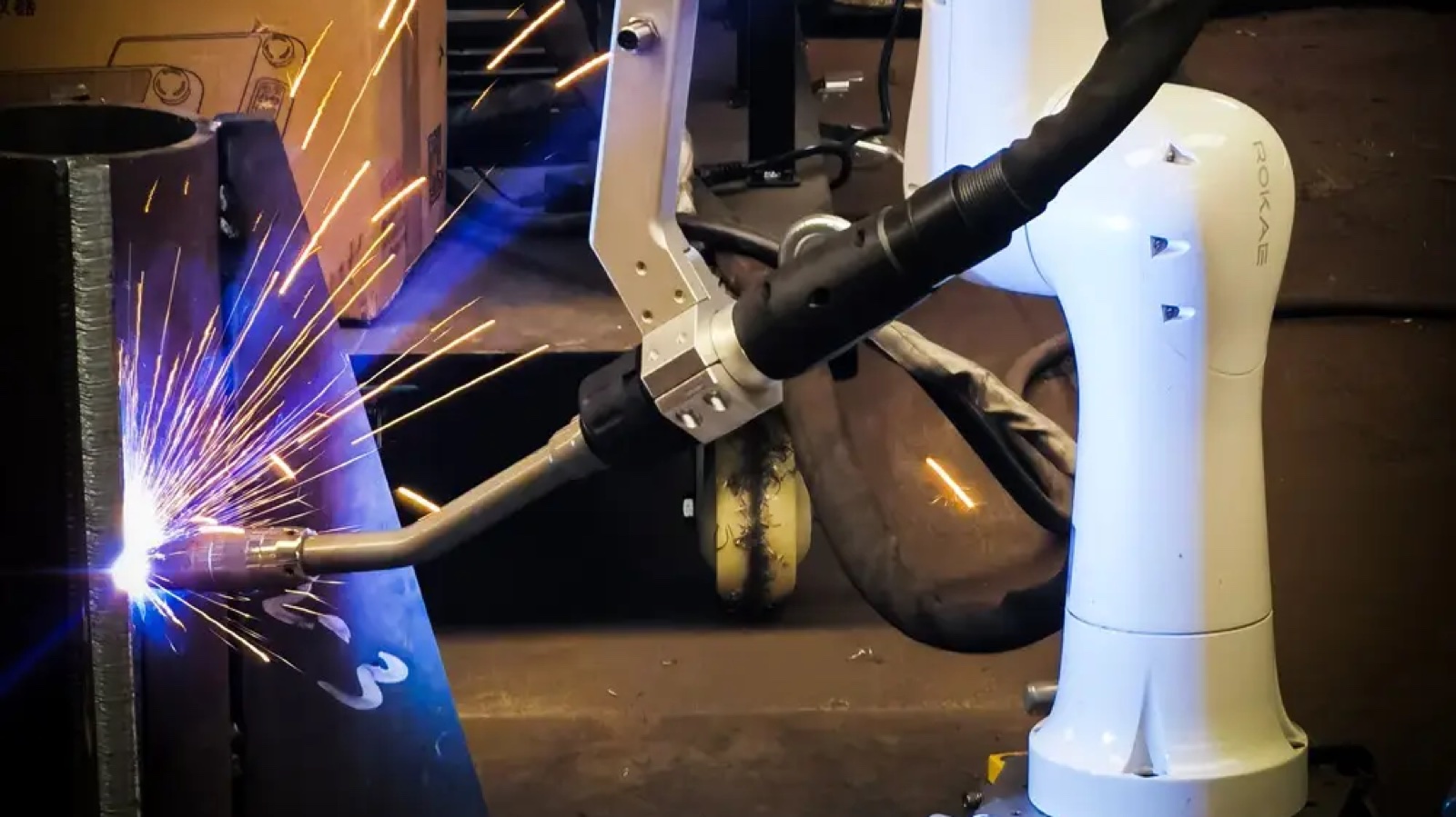
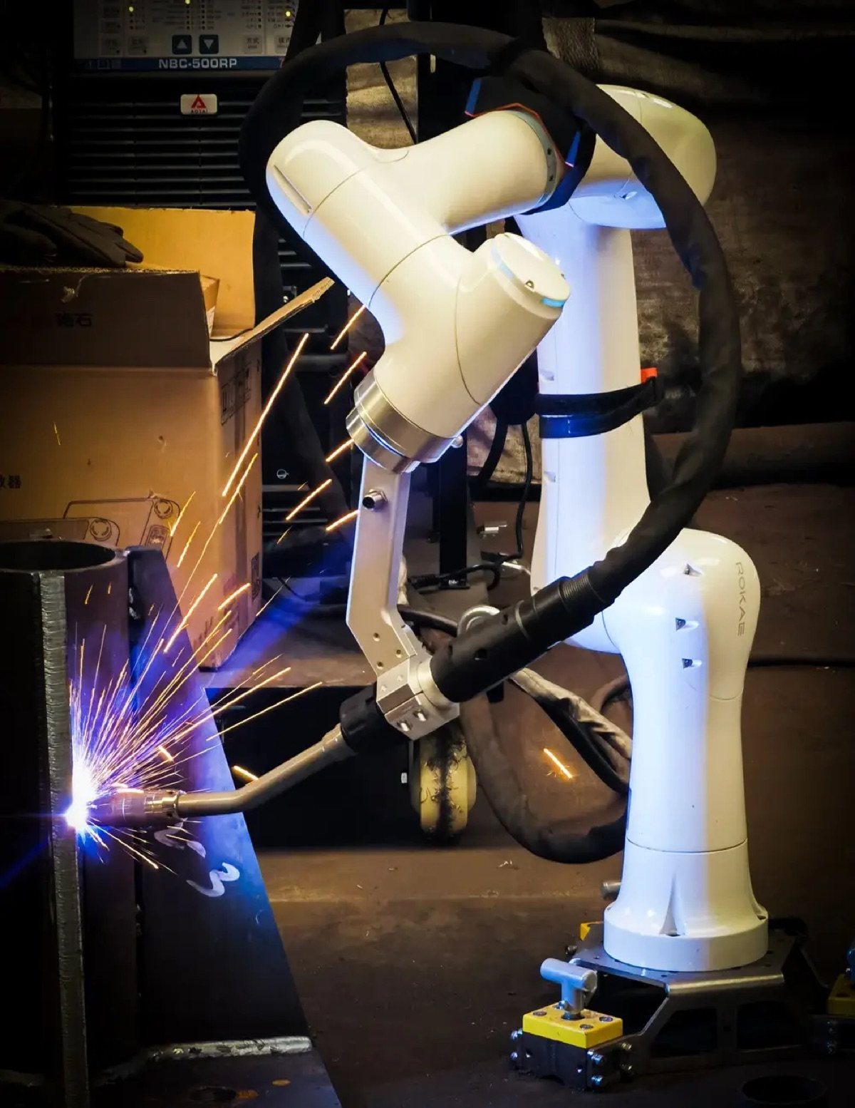
The picture above shows what a real cobot welding cell actually looks like: a collaborative arm on a bench, a 500 amp inverter power source behind it, and a vertical fillet weld on a plate edge throwing short-circuit spatter across the torch dressing. Nothing exotic. That is exactly the job a cobot MIG cell should be built for, and exactly the place where a rushed build shows up later as nozzle wear, cable failures and rejected welds. This walkthrough takes the cell apart subsystem by subsystem and shows what to check before you press start.
Why Cobot GMAW Works for Short Runs
Fabrication shops rarely run one part number for eight hours. They run twenty brackets in the morning and a pallet of frames after lunch. Manual MIG stays unbeatable for one-off, awkward welds, and a hard automation fixture only pays for itself above a few thousand identical seams. A collaborative arm sits in the gap between those two: repeatable enough for the medium run, cheap enough to reprogram between them, and light enough to bolt onto the table the welder already uses. The economics are covered in our comparison of welding cobots and industrial robots. This article assumes that decision is behind you and the build is in front of you.
Start With the Five Subsystems
Every cobot arc cell is five purchases that have to behave as one machine. Treating them as one line item is how shops end up with a robot they are afraid to use.
| Subsystem | What good looks like | Common mistake |
|---|---|---|
| Arm and base | Rigid mounting, rated for actual wrist load at full reach | Bolted to a wheeled cart that shifts under torch contact |
| Power source | CV inverter with remote parameter control from the robot | Adjusting wire speed from a front panel nobody can reach mid-seam |
| Torch and dressing | Light air-cooled torch, cable dressed with service loops | A heavy robot-grade torch with zero slack at the joints |
| Table and fixtures | Repeatable clamps, one known datum, ground clamp on the fixture | Parts tacked by eye and gaps left for the robot to discover |
| Pendant and program | One-button start, clear jog limits, saved parameters | Teach points edited live with the arc still running |
Size the Arm for the Torch Not the Catalog
Cobot payload ratings are quoted at the wrist flange with the center of gravity tucked close to the joint axis. Add a three-meter MIG torch, the wire and gas bundle, and the dressing, and that center of gravity moves three to five hundred millimeters outboard. A 20 kilogram arm becomes a 12 kilogram arm in practice, and the reach you can actually use shrinks with it because the last joint can no longer hold its rated torque at full extension. Two rules prevent the regret: build a mock torch package with the real cable lengths and let the arm hold its worst-case pose at full speed for an hour, checking for sag; and map the far corner of your weld table, not the center, against the reach envelope. If the arm has to lean to reach the seam, it will lean through the seam.
Dress the Cables Like They Will Fail
The fabric-sleeved loom running along the arm in the photo is doing a job most builders ignore until it breaks. On a cobot the torch cable flexes at every joint, thousands of cycles per shift, and the failure mode is not dramatic: the wire bundle kinks inside the jacket, feed stutters, porosity and inconsistent penetration follow, and the welder blames the parameters. Dress it once, properly. Respect the minimum bend radius of the cable, not the sleeve. Leave a service loop at every joint so the bend happens in free cable, not at the strain relief. Put strain relief at both ends and nowhere in the middle, where it becomes a lever arm. Coil spare length away from pinch zones between the arm and its own base. And route the ground cable so it cannot be dragged across the work envelope by the second axis.
Fixturing and Fit Up Decide Quality
A robot repeats exactly what you taught it, which is a blessing on a good fixture and a curse on a bad one. Short-circuit GMAW tolerates a gap of roughly a millimeter on a fillet before you start seeing underfill and cold joints; beyond two millimeters you need weave, stringers or a different process, and a cobot teaching session is not the place to discover that. Fix the presentation before the seam: grind mill scale off the joint faces where the arc must melt through it, as the clean weld line along the plate edge in the photo shows; locate every part against one datum with clamps that return to the same position every cycle; and put the magnetic base and work support where the torch can approach at a 10 to 15 degree push angle without the wrist crossing its own soft limits. If a human would have to persuade that part into place, the robot will persuade it into scrap.
Pick a Transfer Mode Then Tune It
The spatter fan in the photo identifies the process as short-circuit GMAW, the default choice for out-of-position work on thin material. It runs cool and forgiving but spatters, and spatter on a cobot is worse than on a manual station because it lands on dressings, sensors and cable jackets instead of a leather apron.
| Mode | Typical wire | Strengths | Watch for |
|---|---|---|---|
| Short-circuit | 0.8 to 1.0 mm | Low heat, out-of-position, cheap | Spatter, cold laps on fast travel |
| Pulsed | 0.9 to 1.2 mm | One droplet per pulse, cleaner spray region | Needs disciplined gas and stick-out |
| Spray | 1.2 mm and up | High deposition, low spatter above critical current | Too hot for thin plate, flat positions mostly |
On 1.0 mm ER70S-6 with an 82 percent argon, 18 percent CO2 mix, keep stick-out constant at 12 to 15 millimeters, clean or anti-spray the nozzle on a fixed schedule, and treat a spatter change as a process alarm, not housekeeping. If you are still deciding whether arc or laser deserves the cell, the process-level trade-off is in laser versus MIG welding.
Teach Pendant or Offline Programming
Most cobot cells start life hand-guided: grab the torch, walk the seam, press save. That is the right way to prototype and the wrong way to scale, because every teaching minute is a production minute the cell never gets back, and because hand-guided paths carry the wobble of the guiding hand into the weld. When the same seam family comes back week after week, offline programming and a repeatable datum strategy pay for themselves, and the trade-offs are laid out in our piece on offline programming versus teach pendant. One practical bridge between the two: teach one reference part perfectly, then let vision or seam tracking find the actual seam, instead of trusting the fixture to be perfect twice.
Safety in a Shared Workspace
Collaborative arms are sold with power and force limiting under ISO/TS 15066, and for the arm itself that is often genuinely enough at slow speeds. The arc is a different hazard class. Ultraviolet radiation, hot spatter and molten spatter droplets do not care that the robot is force-limited, so put a local shield around the weld point and treat the pendant as a deadman, not a suggestion. Fume extraction is not optional in a cell that runs unattended for hours; the physics of capturing manganese-bearing fume at the source is covered in fume extraction and air quality. And when the cell leaves your shop as a machine, the CE marking route for the whole assembly, not just the robot, starts with CE marking essentials.
Cell Acceptance Checklist
Before the first paid part, walk these ten checks cold:
- Arm holds worst-case torch pose at full speed for an hour with no sag
- Every joint has a service loop; no cable bends tighter than its rated radius
- Wire feeds clean at target speed through the full reach envelope, all poses
- Ground clamp sits on clean metal on the fixture, not on painted table steel
- Two identical parts clamped in sequence land within one millimeter of the taught path
- Short-circuit parameters are saved as a named preset, not left on the panel
- Nozzle cleaning schedule is set and the first cleaning is due before the first break
- Weld-point shield is in place and fume extraction is running at the seam
- Pendant deadman stops motion and arc within the same second
- Program start requires two hands or one deliberate button, never an auto-resume
The Build Is a Welding Problem First
The arm is the easiest part of this cell to buy and the least likely to be the reason it underperforms. Every failure mode in the photo, spatter on the dressing, gaps that defeat the taught path, a cable that kinks at joint three, is a welding and fixture problem wearing robot clothing. Budget your commissioning time the way a welder would: fixturing first, process second, paths last. Shops that invert that order end up with a collaborative robot that collaborates with nobody.
Sources and references
- ISO/TS 15066:2016, Robots and robotic devices — Collaborative robots safety requirements, International Organization for Standardization: https://www.iso.org/obp/ui/#iso:std:iso:ts:15066
- ISO 10218-1:2011, Robots for industrial environments — Safety requirements — Part 1, International Organization for Standardization: https://www.iso.org/obp/ui/#iso:std:iso:10218:-1
- Gas metal arc welding process fundamentals, American Welding Society: https://www.aws.org/
- Short-circuit, pulsed and spray transfer guidance for GMAW, Miller Electric Mfg. LLC: https://www.millerwelds.com/
- Welding, cutting and hot work safety resources, Occupational Safety and Health Administration: https://www.osha.gov/welding-cutting-and-hot-work
Comments (0)
No comments yet.
Sign in to join the discussion.